• The move to the new server is done. There are some software and database maintenance updates in process. This has us passing the hat around to help out. We appreciate any donations. Seriously, even a dollar helps. The payment page may be found here - https://www.audiokarma.org/support.html

Building a poor mans variac (Dim Bulb Tester or DBT)

Is this type of DIY feature usefull?

  • Yes

    Votes: 21 100.0%
  • No

    Votes: 0 0.0%

  • Total voters
    21
  • Poll closed .
Jon_Logan said:
....you can keep the neutral on the receptacle in-tact. In fact, when you break the hot wire you can bridge the gap with your lamp. It'll make handy screw terminals. ...no need for twist loks


I didn't even think of that, but it's certainly an easier way to wire it up than what I was thinking. :thmbsp:

This is similar to what I did, but remember to mary one recepticle and 110, and one as lowered voltage. Or get a switched recepticle and use that.
 
Light bulb limits current, fuse doesn't (until it blows, of course). There CAN'T be any more current flowing than the bulb alone would take (1.3A for a 150W bulb, for instance...). The fuse might let through 100 Amps for 10 milliseconds... The "Poor man's variac" is better than the REAL Variac in this respect. If you use a variac to start up unknown equipment, be sure you have spare fuses for it... if it doesn't have a fuse, you're playing with FIRE...

I believe a lamp will have an inrush current of 30-100 ms duration. Like I posted previously, the fuse is faster.

I guess the way to look at it would be to compare how much energy passes prior to the fuse blowing or the lamp limiting the current (integration of the area under the TIME/CURRENT curve). In either case, with the lamp, current still flows through the deranged unit.
 
Thanks! This thread is helping me understand my tube amps! The search function here at AK is a font of useful information. You guys rock!!!

spideyjack
 
Am I the only one who is so lazy that he thinks it easier to invest a bit more effort up-front, and put multiple lamp sockets in, with a rotary selector switch to choose between them, and thus avoid having to unscrew one bulb and screw in another (and have to keep loose bulbs handy)? You can have 40W, 60W, 100W and perhaps another wattage if you want, all available just at the turn of a switch. You need a bit larger device to accomodate the additional bulbs, though.
 
Hi all. i just built one using these instructions. I want to make sure my connections are right. With the neutral wires tied together and the hot on either terminal on the light socket as instructed how is the bulb supposed to light and how does this limit voltage? My electrical knowledge is pretty limited so be gentle.

Thanks,

John

Adding on: A light just came on in my head and in the tester. Plugged a lamp into it and it functions properly. Can someone explain how this works? When I test the receptical I get 118 volts. Why is the the lamp that I plug into it dim?

Adding on again: Just realized something needs to be pluged in to complete the circuit. With a 15W bulb in the device and a lamp pluged in I get about 40 volts.
 
Last edited:
For 30 years I've used a 100 watt bulb to bring up amplifiers. Most of them were in the 200W/C range with 5A fuses in the power supplies. In this time I've seen the light bulb glow bright 100's of times due to shorted outputs. Never once has a fuse blown. A 100 watt bulb reads about 11 ohms when cold. I could not find the time current curve for an AGC fuse, but it would seem that the fuse must be slower than a bulb or the fuse would clear. I'm assuming the bulb must limit the current enough, even when it is cold, to stay below the fuse curve, long enough for the bulb to heat up.

I do agree that current flows through the damaged unit. In the case of the amp, primary current in the xfmr is limited to less than 2 amps which is within the rating of the xfmr. The fault (shorted outputs) sees a couple amps but almost no voltage and hence very little power.

I believe a lamp will have an inrush current of 30-100 ms duration. Like I posted previously, the fuse is faster.

I guess the way to look at it would be to compare how much energy passes prior to the fuse blowing or the lamp limiting the current (integration of the area under the TIME/CURRENT curve). In either case, with the lamp, current still flows through the deranged unit.
 
Last edited:
Poor Man’s Variac - Bulb Safety

The construction of a Series Lamp unit is quite simple but
Please, Please put a protective shield around your bulb on your “Series Test Lamp” / “Dim Bulb Tester” / “Poor Man’s Variac.”

I'm an electrician & I have been involved with the tragic consequences of bulbs without shields.

My father (also an electrician) wired an Earth Leakage Circuit Breaker / Safety Switch / Ground Fault Interrupter (same thing different names around the world) at a residence. The resident also wanted to fit one on the shed but wouldn't until he got permission from the trust fund that ran the farm side of the property.

An hour or so after my father left the gentleman climbed onto a truck with a lead light that was missing the shield. He bumped the bulb against the metal back, shattered the glass & the live filament holder sticking out touched the truck back & he was killed.

His wife was almost shocked when she came to check on him. He probably would be alive today if he had plugged the light into his house power. Instead a simple, cheap light bulb left his wife to raise several small children on her own.

A broken bulb will have the metal arms that hold the filament sticking out ready to fry you. One will be Live / Hot / Active & the other Neutral / Cold. Please fit either a metal cage from a lead light or a PVC pipe collar with a few holes drilled in it for visibility & cooling.

A little mechanical protection could save a fatality or serious shock. This is especially important on lamps that are portable or easily knocked over.

Regards,
Brian.
 
I would not reccomend using a 15 amp fuse on a test device...use something closer to the equipment rating so it blows QUICK if there's a short. We have a test cord with a 4 amp fuse in it.

I made a short test lamp out of an old photoflood fixture and spliced it in series with an extension cord...has been very helpful in troubleshooting equipment with shorted transistors.

Nice project. But, one comment:

A "Variac" is a brandname of variable transformer. The term has become generic for just about any hand-adjusted, power line transformer. But, a lightbulb rig is >not< a "variac".

In fact, a variac is often used in conjunction with a lightbulb rig. My own bench is set up variac > bulb > breaker > V/A/W meter > DUT. I'll try to find a pic.

-k
 
Wow, only six posts and every one of them were identical. (As well as a PM directly to me, and I suspect everyone else that posted a home brew Dim Bulb Tester) If it wasn’t for its safety concerns, it would be classed as spam, however:

A workbench, especially one setup for testing and repairing tube amps, has far more dangers than a 110 light bulb. Charged caps and whatnot…)
Besides a home brew PVC shield introduces more dangers than it solves.

Some of these light bulbs will get very hot, and in close proximity to PVC is far more dangerous than the remote possibility of a broken bulb, due to the dangers of fire, and toxic smoke. I’ll risk the broken bulb, thank you very much.

The accident you describe, while tragic, is definitely not a common accident, and is pretty remote. I’ll worry about the real dangerous stuff and simply use my tester carefully as I always do.


The construction of a Series Lamp unit is quite simple but
Please, Please put a protective shield around your bulb on your “Series Test Lamp” / “Dim Bulb Tester” / “Poor Man’s Variac.”

I'm an electrician & I have been involved with the tragic consequences of bulbs without shields.

My father (also an electrician) wired an Earth Leakage Circuit Breaker / Safety Switch / Ground Fault Interrupter (same thing different names around the world) at a residence. The resident also wanted to fit one on the shed but wouldn't until he got permission from the trust fund that ran the farm side of the property.

An hour or so after my father left the gentleman climbed onto a truck with a lead light that was missing the shield. He bumped the bulb against the metal back, shattered the glass & the live filament holder sticking out touched the truck back & he was killed.

His wife was almost shocked when she came to check on him. He probably would be alive today if he had plugged the light into his house power. Instead a simple, cheap light bulb left his wife to raise several small children on her own.

A broken bulb will have the metal arms that hold the filament sticking out ready to fry you. One will be Live / Hot / Active & the other Neutral / Cold. Please fit either a metal cage from a lead light or a PVC pipe collar with a few holes drilled in it for visibility & cooling.

A little mechanical protection could save a fatality or serious shock. This is especially important on lamps that are portable or easily knocked over.

Regards,
Brian.
 
I built / "assembled" one of these not too long ago out of curiosity. I "tested" several amps I own and for the most part, experienced "expected" results - (sudden/fast flash and then dim) But for ONE particular Amp, the results were quite different!


B-
 
Last edited:
Can This Work As A Variac?

I built this thinking I could just use the switch type dimmer instead of a light bulb as the voltage adjustment. It has 116 volts when you first plug into wall, then when you first plug in anything, drill, dremel etc, it instantly drops to about 9V with the switch off, 1st stage is 25V, 2nd=40V, 3rd = 56V and finally 4th (Highest Setting) is 116V. It also, gradually climbs to the votage differences. So my question is, will this work well as a variac for bringing up tube amps?
 

Attachments

  • VARIAC 002.jpg
    VARIAC 002.jpg
    57.7 KB · Views: 107
Last edited:
Not a good idea. Typical AC dimmers alter the wave form of the AC voltage to reduce voltage. The transformers in your stereo gear can't handle the altered waveform.

- Pete
 
Not a good idea. Typical AC dimmers alter the wave form of the AC voltage to reduce voltage. The transformers in your stereo gear can't handle the altered waveform.

- Pete

:thmbsp:Thank you for that information, I will switch it to the light bulb type as specified.
 
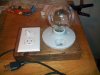
You don't want to know how much stuff I did without one of these, but I managed to get it done before learning my lesson, so to speak. Oh wait, no I did lose a rectifier tube once. Anyway, even though these are simple and all over the place, I was wishing for some more examples when I went to build, so I'm adding mine to the pile. Simple & sweet, in a routed-out piece of scrap with a 1/4" plywood bottom.
 

Attachments

  • kdk_0396.jpg
    kdk_0396.jpg
    90.2 KB · Views: 419
I built this thinking I could just use the switch type dimmer instead of a light bulb as the voltage adjustment. It has 116 volts when you first plug into wall, then when you first plug in anything, drill, dremel etc, it instantly drops to about 9V with the switch off, 1st stage is 25V, 2nd=40V, 3rd = 56V and finally 4th (Highest Setting) is 116V. It also, gradually climbs to the votage differences. So my question is, will this work well as a variac for bringing up tube amps?
http://www.audiokarma.org/forums/showpost.php?p=3126873&postcount=12

Not good for electronic equip.
 
You don't want to know how much stuff I did without one of these, but I managed to get it done before learning my lesson, so to speak. Oh wait, no I did lose a rectifier tube once. Anyway, even though these are simple and all over the place, I was wishing for some more examples when I went to build, so I'm adding mine to the pile. Simple & sweet, in a routed-out piece of scrap with a 1/4" plywood bottom.

Yours looks really nice, but I would advise back-boxes rated for electrical use for the lamp holder and switch\receptacle. Electrical devices and wood don't always play nice together.:thmbsp:
 
...I would advise back-boxes rated for electrical use for the lamp holder and switch\receptacle...:thmbsp:
Noted. I did do my best with heat shrink to make sure I don't end up with an electrified board... and I've got the earth wired up which I guess could help in certain scenarios.
 
It's probably been done before, but this is what I was thinking. Use several small bulbs in plug-in lamp holders, that way you can increase the current on the fly just by plugging in more bulbs.

Then, there is a "full power" switch to short across the lamp bank, half the load receptacle is powered by the lamp bank, the other half is powered up by the "on" switch. The latter I'm undecided...might be better off to avoid the possibility of plugging the DUT into the wrong half of the receptacle.
 
Last edited:

The link makes its point. There is one minor problem. A phase angle controller (light dimmer) works just the opposite of what is shown. The dimmer delays the firing of the triac any where from about 45 -160 degrees from the zero crossings. The demo shows the firing ocurring at zero and 180 degrees and then turning off at some point in the cycle. That would be ok if it would work, but once a triac is fired, it stays on until the current through it goes to zero.

Here is a more accurate link. The top one is a typical light dimmer, the bottom one is a DC controller. Note that any type of phase angle controller that tries to drive an inductive load such as a transformer must precisely control the positive and negative cycles for the exact same time. If it has a minor difference the result looks like a DC bias on the load and it would run quite hot. An example is a dimmer for the low voltage lighting that is used in landscaping. The dimmer controls the primary of the step down transformer. These types of dimmers are precise controllers to avoid the problem of DC offset.
Phase angle controller
 
Last edited:
Back
Top Bottom