• The move to the new server is done. There are some software and database maintenance updates in process. This has us passing the hat around to help out. We appreciate any donations. Seriously, even a dollar helps. The payment page may be found here - https://www.audiokarma.org/support.html

Building a scratch version of Dave Gillespie's 8600 mod

scootsity5

AK Subscriber
Subscriber
Hello all,

I was told to stop asking questions in the main thread, and instead create my own build thread. So, I am!

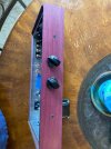
Here's the deal, a few years ago, we acquired a beat up telefunken console. It was pretty much toast. So, I took out the speakers, turned the turntable drawer into a real drawer, added a ton of internal support structures, and installed rack rails where the speakers used to be. Those rails have a nice PDU in them, with remote triggers and LEDs (so many of the original buttons still do stuff).

Now, I need to build an amp and I wanted to keep it something of a nod to the original, plus, I got all these telefunken tubes that test good. So, the original was a mono, push-pull EL84 job with a 12AX7 pre. So, I got all the amp tubes I need that supposedly test good for this build.

I've previously built a relay based passive pre that I'll use again and hide in the rack, and I'll probably use one of Wyn Palmer's v4 preamp for the phono, because I built one of those into the passive pre last year with very positive results.

Happy to post pictures of that pre, it currently drives my engineer amp (aka DCPP) designed by Pete Millet.


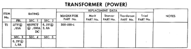
OK. So, the amp: as I said, my goal is to reuse what I can from the telefunken. It used diodes for rectification, I see no need to get fancy there, so I'm leaning toward a cheap bridge rectifier. Then, I need a transformer capable of just about 190V at 100-200mA. Matt at musical power supplies makes just such a transformer. (I guess I could also go 380V and use a pair of rectifier diodes, but I'm leaning towards a bridge that I can chassis mount). The telefunken transformer has been through some ****. I also dropped a lead and shorted it - and it sizzled. It still tests okay, but I'm skeptical.

Then, I'll get a pair of Matt's guitar amp output transformers as one of my design constraints is to keep it as cheap as I can.

I was also eyeing a torroidal transformer that could work for power, too.

For those who have bought a power transformer, how much power did you end up needing? My guess was about 50-60VA? Is that about right, or am I way off?

The telefunken chassis is giant and has a ton of real estate dedicated to the tuner and dynamics, so I'm going to build it into a budd or Hammond chassis. Maybe some walnut veneer.

Oh, one last design goal, the original telefunken console had a pair of tubes that glow green and make a sort of oval shape that grows and shrinks as you get closer to proper tuning for a station. I may try to re-purpose those to basically grown and shrink with music. I haven't really even found much of a data sheet for them, so that's the lowest priority, if I get there.
 
Register to hide this ad
Howdy! So glad to see a new build thread.

I assume the 190V spec on the transformer comes from subtracting the 6CA4 rectifier tube voltage drop (about 20V) then multiplying 190VRms by 1.414 to get 268V? Keep in mind that transformer voltage specs vary widely- some few guarantee that rated voltage under load, for almost all others that voltage spec is for completely unloaded, and will sag significantly to a lower voltage under the rated load current. Using the original 8600 Sams, they are using a 460VCT transformer (230V - 0 - 230V) rated at 90mA, but because one filament winding is used to buck the primary (and is passing much lower current) Dave G increased the load to 100mA and this transformer handles it well. If we took the 230V (unloaded) * 1.414 we get 325V, and after a 20V drop in the 6CA4 you would think the high voltage at the first cap would be 305V, but it's not- it's more like 270, suggesting 35V sag in the HV primary. So rebuilding this same amp with diode rectification, you would be looking for more like a 215V - 0 - 215V or 430VCT secondary, with a 100mA or better rating. (You want to go on filament and HV current ratings rather than overall VA.) More is better- Higher than needed current rating just means it will run cooler, and as far as voltage, It's much easier to bleed off a little extra voltage with a dropping resistor than it is to suffer with too low of B+. Adding an extra power dropping resistor also gives opportunity to add another CRC filter stage, never a bad thing.

1775778259051.png

The diode of choice for solid state HV rectification in amps like this is usually the 1000V PIV rated 1N4007, which is almost always up to the task. If you use a bridge, make sure the PIV rating is 1000V minimum, as it will be seeing at least twice the Vpp of the HV secondary.

For cheap OPTs, it's hard to beat the P-T31 at about $22 a pop, but even the cheapest Chinazon outputs are as good as those. The MPS transformers are apparently pretty good- They will have better bass response than the P-T31 easily, and with the good amount of global negative feedback (17dB) that Dave's design uses, even the guitar amp versions can be made flat enough through 20kHz.

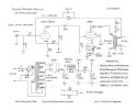
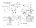
The second incarnation of Dave's design uses adjustable bias. Do you intend to do that, or are you working off of the gen 1 schematic?

Green "eye" tubes are fun to play with. Tons of datasheets on all tubes over at Frank's. If you can't find one call it out and there are lots of folks here that have them or can get them.

dcgillespie_8600_schematic_Rev_2.jpg
 
Howdy! So glad to see a new build thread.

I assume the 190V spec on the transformer comes from subtracting the 6CA4 rectifier tube voltage drop (about 20V) then multiplying 190VRms by 1.414 to get 268V? Keep in mind that transformer voltage specs vary widely- some few guarantee that rated voltage under load, for almost all others that voltage spec is for completely unloaded, and will sag significantly to a lower voltage under the rated load current. Using the original 8600 Sams, they are using a 460VCT transformer (230V - 0 - 230V) rated at 90mA, but because one filament winding is used to buck the primary (and is passing much lower current) Dave G increased the load to 100mA and this transformer handles it well. If we took the 230V (unloaded) * 1.414 we get 325V, and after a 20V drop in the 6CA4 you would think the high voltage at the first cap would be 305V, but it's not- it's more like 270, suggesting 35V sag in the HV primary. So rebuilding this same amp with diode rectification, you would be looking for more like a 215V - 0 - 215V or 430VCT secondary, with a 100mA or better rating. (You want to go on filament and HV current ratings rather than overall VA.) More is better- Higher than needed current rating just means it will run cooler, and as far as voltage, It's much easier to bleed off a little extra voltage with a dropping resistor than it is to suffer with too low of B+. Adding an extra power dropping resistor also gives opportunity to add another CRC filter stage, never a bad thing.

View attachment 3738938

The diode of choice for solid state HV rectification in amps like this is usually the 1000V PIV rated 1N4007, which is almost always up to the task. If you use a bridge, make sure the PIV rating is 1000V minimum, as it will be seeing at least twice the Vpp of the HV secondary.

For cheap OPTs, it's hard to beat the P-T31 at about $22 a pop, but even the cheapest Chinazon outputs are as good as those. The MPS transformers are apparently pretty good- They will have better bass response than the P-T31 easily, and with the good amount of global negative feedback (17dB) that Dave's design uses, even the guitar amp versions can be made flat enough through 20kHz.

The second incarnation of Dave's design uses adjustable bias. Do you intend to do that, or are you working off of the gen 1 schematic?

Green "eye" tubes are fun to play with. Tons of datasheets on all tubes over at Frank's. If you can't find one call it out and there are lots of folks here that have them or can get them.

View attachment 3738936
Thanks for that! I'll rethink my math a bit.

The telefunken's transformer may actually be up to the job. I'll play with it again this weekend.

I'm a little concerned about the sizzle I heard when I was playing with it (I was trying different connections on the primaries to see if using one of the primary taps for a different mains voltage got closer to a voltage that would rectify nicely to 270vdc when it started sizzling). Again, it now tests okay, so I'm not sure if I just cooked some glue or did any real damage.

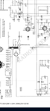
The rectified voltage off the telefunken transformer in the schematic is 252mA at 108mA.

I tried a few different taps on the primary and I'm pretty sure with 120v on one of them, I got into the 220-230 range.

Yes, plan to have bias pots. I found some 100ohm linear 3 turn trim pots that panel mount. I thought that'd do the job.

Thanks!
 

Attachments

  • Screenshot_20260409-212739.png
    Screenshot_20260409-212739.png
    91.5 KB · Views: 24
  • Screenshot_20260409-212727.png
    Screenshot_20260409-212727.png
    113.5 KB · Views: 24
Last edited:
Unfortunately the screenshots of the schematic are unreadable- AK downsamples quite a bit. If you included the model number, or the link to the model and schematic on Radiomuseum it would be helpful to see more information about the stock transformer.

It sounds like you have a shot at making it work for a DGSE-1 if you can see 220-230VAC (RMS) unloaded. The real indicator will be what the filament voltage is reading when the primary is connected that way. Unloaded it will probably be in the 7V AC RMS range, but you want the filaments (when loaded) to be running as close to 6.3V as you easily can. You don't want a primary configuration that achieves your HV goal, but has to run the filaments above about 6.6V, or below 6.0V as that is not a win long term. No real way to tell how reliable the transformer will be (if damaged) until it's under load for awhile.

Those trim pots- do you know the power rating? One per 6BQ5 will be passing about 50mA through the pot, dissipating about .25W so they really should be rated for at least 1/2 watt to be reliable.
 
Hello all,

I was told to stop asking questions in the main thread, and instead create my own build thread. So, I am!

Here's the deal, a few years ago, we acquired a beat up telefunken console. It was pretty much toast. So, I took out the speakers, turned the turntable drawer into a real drawer, added a ton of internal support structures, and installed rack rails where the speakers used to be. Those rails have a nice PDU in them, with remote triggers and LEDs (so many of the original buttons still do stuff).

Now, I need to build an amp and I wanted to keep it something of a nod to the original, plus, I got all these telefunken tubes that test good. So, the original was a mono, push-pull EL84 job with a 12AX7 pre. So, I got all the amp tubes I need that supposedly test good for this build.

I've previously built a relay based passive pre that I'll use again and hide in the rack, and I'll probably use one of Wyn Palmer's v4 preamp for the phono, because I built one of those into the passive pre last year with very positive results.

Happy to post pictures of that pre, it currently drives my engineer amp (aka DCPP) designed by Pete Millet.


OK. So, the amp: as I said, my goal is to reuse what I can from the telefunken. It used diodes for rectification, I see no need to get fancy there, so I'm leaning toward a cheap bridge rectifier. Then, I need a transformer capable of just about 190V at 100-200mA. Matt at musical power supplies makes just such a transformer. (I guess I could also go 380V and use a pair of rectifier diodes, but I'm leaning towards a bridge that I can chassis mount). The telefunken transformer has been through some ****. I also dropped a lead and shorted it - and it sizzled. It still tests okay, but I'm skeptical.

Then, I'll get a pair of Matt's guitar amp output transformers as one of my design constraints is to keep it as cheap as I can.

I was also eyeing a torroidal transformer that could work for power, too.

For those who have bought a power transformer, how much power did you end up needing? My guess was about 50-60VA? Is that about right, or am I way off?

The telefunken chassis is giant and has a ton of real estate dedicated to the tuner and dynamics, so I'm going to build it into a budd or Hammond chassis. Maybe some walnut veneer.

Oh, one last design goal, the original telefunken console had a pair of tubes that glow green and make a sort of oval shape that grows and shrinks as you get closer to proper tuning for a station. I may try to re-purpose those to basically grown and shrink with music. I haven't really even found much of a data sheet for them, so that's the lowest priority, if I get there.
transformers - You may want to shoot Matt a question (Musical Power supply's ) -about a Small upgrade to the guitar options of his transformers -In a correspondence with him - He mentioned a upcoming option ( SE -12 hF's ) for Better Output transformers - (May I think )
I was trying to encourage anyone who is doing a scratch build to - support another option ( Interest at least ) for - perhaps not top tier options ,but something in the middle - He built for me a version of the OT - SE10 - HF's- For a variation of Dave DGSE1- with 6AQ5 as the output tubes ) - and I find the sound VERY nice - it is least worth a question - he seems quite responsive - on Line
 
Last edited:
transformers - You may want to shoot Matt a question (Musical Power supply's ) -about a Small upgrade to the guitar options of his transformers -In a correspondence with him - He mentioned a upcoming option ( SE -12 hF's ) for Better Output transformers - (May I think )
I was trying to encourage anyone who is doing a scratch build to - support another option ( Interest at least ) for - perhaps not top tier options ,but something in the middle - He built for me a version of the OT - SE10 - HF's- For a variation of Dave DGSE1- with 6AQ5 as the output tubes ) - and I find the sound VERY nice - it is least worth a question - he seems quite responsive - on Line
He always seems to be tinkering and improving. I'll ask him. Thanks for the tip. He's also suggested a number of books to me to learn more about output transformer design.
 
This weekend, I went to axpona and didn't get a chance to tinker with the telefunkens transformer. Will report back next weekend.
 
Well, my spouse was laid off, so I think unnecessary projects are on hold for a little bit. I'll probably take a few weeks away from this one until we figure everything out.

In othet news, Matt at musical power supplies of course gave some great adbice, per usual.

Now that the rectification is silicon, I'm considering upping the amount is smoothing capacitance right after the diodes. But that might be entirely unnecessary.

Thanks all for the guidance thus far.
 
I'm sorry to hear about the challenges life is throwing your way. Not fun. Hope you all are all well, hang in there- the stress can be overwhelming. Let us know when you can come back around and spend some time with us- it's always nice to hang out, even just to chew the fat on the design. (My designs spend months rent free in my head before I work out all the kinks and actually order parts). It's a fun diversion when life gets tough. We're here for you.

The first capacitor is usually limited to prevent arcing in the rectifier tube. Diode rectification always enables more capacitance because the risk of arc is eliminated- but there is a limit- Excessively large bypass capacitors cause larger current spikes to appear in the HV secondary through the diodes- those spikes in current can cause transformer buzz and more heating in the winding, and induce more noise in the circuits around the transformer leads, so going larger has diminishing gain. The choke, enabling a C-L-C filter stage, is what really smooths out the ripple. Even with diodes, there is not much to gain by going higher than 47uF, but if you must, try to keep it under 100uF or so. The choke is a big win, and another 47uF after the choke- the ripple will be quite minimal.
 
I'm sorry to hear about the challenges life is throwing your way. Not fun. Hope you all are all well, hang in there- the stress can be overwhelming. Let us know when you can come back around and spend some time with us- it's always nice to hang out, even just to chew the fat on the design. (My designs spend months rent free in my head before I work out all the kinks and actually order parts). It's a fun diversion when life gets tough. We're here for you.

The first capacitor is usually limited to prevent arcing in the rectifier tube. Diode rectification always enables more capacitance because the risk of arc is eliminated- but there is a limit- Excessively large bypass capacitors cause larger current spikes to appear in the HV secondary through the diodes- those spikes in current can cause transformer buzz and more heating in the winding, and induce more noise in the circuits around the transformer leads, so going larger has diminishing gain. The choke, enabling a C-L-C filter stage, is what really smooths out the ripple. Even with diodes, there is not much to gain by going higher than 47uF, but if you must, try to keep it under 100uF or so. The choke is a big win, and another 47uF after the choke- the ripple will be quite minimal.
That's good to know. The Telefunken had a choke that's a but bigger, given that i may have a little extra voltage to burn, I may experiment with that, too.

Thanks for the kind words.
 
I ended up corresponding with Matt at mpp and as always, he provided a wealth of information.

I'm still holding off for now, but I think I've got the design generally figured out. If I get a few minutes on my lunch tomorrow, I'll write it up.
 
Hi everyone.
This DGSE1 is my first scratch build.
I’m having trouble going from schematic to layout which I’m sure is common for beginners.
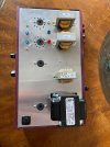
This is what I have so far but I’m confused on wiring the rest of the 12AX7 or ading more tag strips around it? Any advice is welcome.

Thanks,
Ron
 

Attachments

  • IMG_1836.jpeg
    IMG_1836.jpeg
    275.2 KB · Views: 38
  • IMG_1802.jpeg
    IMG_1802.jpeg
    94.3 KB · Views: 38
Hi- Glad you're back. Hope all are well.

Planning out the terminal strips and point to point wiring strategy on a custom build is always a challenge. I have found the easiest way to tackle this requiring the least amount of tear-up and redo is to sketch it out first on paper. Once you have the pin numbers identified it goes pretty quickly. If you do it life size, you can place the actual terminal strips and components on the drawing to see how long the runs will be and whether they will fit. Make mistakes, erase, iterate, fine tune, and optimize. Paper and pencil are cheap! Once you have this map, building is a piece of cake because you don't have to stop and figure every connection out again over and over.


Star_Ground_Channel.jpg
 
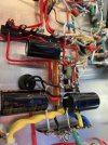
Well I’ve spent a bunch of $$ on the DG-SE1 scratch build. Plugged into the dim bulb and smoked the 820 ohm 1 watt resistor. Powered off immediately. I did the best I could as a novice but obviously heartbreaking.
I’m gun shy now.
I’m will to ship it and pay someone the fix this for me.
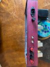
Here are my pics… thanks guys!
Ron
 

Attachments

  • IMG_1877.jpeg
    IMG_1877.jpeg
    279.3 KB · Views: 57
  • IMG_1901.jpeg
    IMG_1901.jpeg
    283.1 KB · Views: 48
  • IMG_1903.jpeg
    IMG_1903.jpeg
    277.8 KB · Views: 37
  • IMG_1902.jpeg
    IMG_1902.jpeg
    291.7 KB · Views: 36
  • IMG_1904.jpeg
    IMG_1904.jpeg
    264.5 KB · Views: 44
  • IMG_1802.jpeg
    IMG_1802.jpeg
    94.3 KB · Views: 55
Hi- Glad you're back. Hope all are well.

Planning out the terminal strips and point to point wiring strategy on a custom build is always a challenge. I have found the easiest way to tackle this requiring the least amount of tear-up and redo is to sketch it out first on paper. Once you have the pin numbers identified it goes pretty quickly. If you do it life size, you can place the actual terminal strips and components on the drawing to see how long the runs will be and whether they will fit. Make mistakes, erase, iterate, fine tune, and optimize. Paper and pencil are cheap! Once you have this map, building is a piece of cake because you don't have to stop and figure every connection out again over and over.


View attachment 3760904
I'm not back, this is someone else building a scratch amp!

I'm delighted someone else took up the mantle. I'm doing some circuit redesign to cut cost and revisit in a few months when our finances improve!
 
Well I’ve spent a bunch of $$ on the DG-SE1 scratch build. Plugged into the dim bulb and smoked the 820 ohm 1 watt resistor. Powered off immediately. I did the best I could as a novice but obviously heartbreaking.
I’m gun shy now.
I’m will to ship it and pay someone the fix this for me.
Here are my pics… thanks guys!
Ron


Resistors are cheap. You smoked the best thing you could have smoked. Don't get discouraged!

Point to point builds are harder!

Did you do what wparks suggested and sketch out the circuit? If so, I have two questions, does your sketch exactly match what you built? If so, post a picture of the sketch. That'll be easier for us to look at than the amp itself.
 
Last edited:
Thanks. I did not sketch I just took it a section at a time. My first time so I wasn’t sure where to put tags. Keeping all grounds to star point.
 
Filaments/heaters work. Dim bulb didn’t glow until tubes were warm enough so I’m assuming it’s something with the B+? Had some hum from the speakers at the same time. As Cajun man would say…”Frus-Tra-Tion!”
 
Back
Top Bottom