• The move to the new server is done. There are some software and database maintenance updates in process. This has us passing the hat around to help out. We appreciate any donations. Seriously, even a dollar helps. The payment page may be found here - https://www.audiokarma.org/support.html

Building a scratch version of Dave Gillespie's 8600 mod

That's going to be WAY overkill for this particular amp. You are shooting for 230V - 0 - 230V for a rectified voltage in the 270V range, this one is 400V, so you are going to be dropping a LOT of power (like 12-15 watts) to get down to any reasonable voltage. The transformer will be really huge for this design.
This amp overall only pulls about 100mA, so there are many new and used smaller tube power transformers that will work for this.
 
400 * 0.7 = 280
Less a volt or two for the drop of the diodes.

In the application notes, the 400v taps are in parallel.

At 470 mA, it's down to 380V. So at 100 mA, it's probably in the 390V ish range.

390 * 0.7 = 273
Less a volt or two for the drop from the diodes.

Yes, it's a 200VA transformer, which is overkill, but it's the smallest they got.

What am I missing here?
 
the 0.7 Where is that coming from? In going from RMS to peak you use 1.414. (then you start derating for loading.)

400V RMS = 565V peak (maximum ideal unloaded DC you would see out of your rectifier diodes.)
 
You will destroy a torroid transformer using half wave rectification.
I had a brain fart.

Definitely not planning on doing anything with half wave rectification.

I had been working on a control circuit that is all half wave rectifiers and just didn't think it through.

I'm ordering a 100VA, 200 V torroid transformer for like $40 from antek.

Thanks.
 
I got all my components. I usually kinda bounce back and forth between construction and case work. This time, because of how I want it to look, I'm going to have to do all the casework first, so it may be a little bit before I post the build again.
 
Has anyone built one of these amps with a ccs instead of the trimpots? I am debating using an LM317, similar to the RH84.
 
I suppose you could but being class A, its pretty much constant current anyway. You could eliminate the pot and just use a fixed resistor to set the bias but you're somewhat at the mercy of tube variables. Realistically if the value is properly chosen it won't make that much difference so long as you aren't using tubes that bias weirdly but it may cost a tiny bit of power depending on how any individual tube biases. My SE amp doesn't have pots.
 
I suppose you could but being class A, its pretty much constant current anyway. You could eliminate the pot and just use a fixed resistor to set the bias but you're somewhat at the mercy of tube variables. Realistically if the value is properly chosen it won't make that much difference so long as you aren't using tubes that bias weirdly but it may cost a tiny bit of power depending on how any individual tube biases. My SE amp doesn't have pots.
Interesting. Yours is just a fixed resistor?
 
Mine isn't this schematic, I started with an AMP-197 and went a slightly different route but it ended up that the stock 82 (I think) ohm shared resistor biased it close enough to ideal that I didn't bother putting in pots or test points. Thats one resistor for both tubes, so it means it wants a matched pair. I'm just running the original Magnavox tubes which seem to be just fine.
 
Dave Gillespie's "version 1" schematic was single bias resistor (for each 6BQ5).

According to Dave, being able to operate at 49mA cathode current (~44mA plate) is the "sweet spot" for best linearity and lowest distortion for the 6BQ5, so either adjustable bias or fixed current source is the "optimal" way, but I agree, self bias is elegant and simple as long as you have two fairly decent tubes.


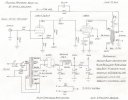
dcgillespie_8600_schematic_Rev_1.jpg
 
yeah there is ideal and there is close enough, in most cases you won't ever notice its not ideal without test gear. Part of what I was aiming for with mine was low effort and low cost for something I quite literally picked up on the side of the road. It didn't get new filter caps or tubes, it got the absolute cheapest transformers I could find, no choke, no test points, no trimmers, etc. It works fine, there are things that could probably be better but I figured the effort vs reward equation was beginning to tip so I stopped.
 
The lm317 data sheet doesn't have a good demonstration of how to use it as a ccs. Do you have a good source for the math? I looked at the rh84, which I'm pretty sure is pretty close, but I'm unclear how he selected 27 ohms between the output and adjust of the lm317.

Thanks!
 
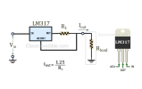
That picture is of the LM137, a negative regulator so could be confusing.

Just Google "LM317 as a current source". The comment is correct though- 1.25V/R1. In the RH84 amp he ties adjust to ground, so the "load" is R1, fixed current is 1.25V/27 = 46.3mA cathode current. Vin will float up to whatever positive cathode voltage the tube wants to be able to flow that current.

1784266032816.png
 
Thanks, I actually found it after I asked. The data sheet I was looking at didn't have any circuit diagrams. Thanks. I inferred the simple layout from the rh84, but just wasn't sure how it was set. Thank you!
 
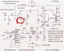
I'm working on a schematic for my mods. OK, I'm 90% sure I know the answer to this, but the 150k resistor off the 255v should not connect to the cathode of the 12ax7, above the 820 r resitor to ground, right?

It's a little unclear in the schematic. I don't think that voltage would be possible, but just thought I'd make sure .

Thanks!4527.jpg
 
In Dave's schematic, if the lines cross and there is no "hop-over" (like the one jumping over the grid right above left of that) they are connected.
Yes, the 150K connects to the cathode.
I always draw dots on the crossings of Dave's schematics. In fact, I'm a "dot nut" and put dots at every T as well.
 
Back
Top Bottom