• The move to the new server is done. There are some software and database maintenance updates in process. This has us passing the hat around to help out. We appreciate any donations. Seriously, even a dollar helps. The payment page may be found here - https://www.audiokarma.org/support.html

Building Again--Marblewood 6V6 SEUL

Dave451

AK Subscriber
Subscriber
After completing my second build of Dave Gillespie's Fisher SA-100 clone, I guess I was on a roll and was inspired to build again by another AK thread looking for a 'standard design' for tube amps. The thread mentioned the subject Cascade Tubes single-ended 6V6 amp. The amp is described by Matt at Cascade as a "simple design suitable for a first build."

I was intrigued because I have a nice group of 6V6GT/G JAN tubes on hand and I've been looking to try either a SE or push/pull amp that uses them. I had a Hammond power transformer that would fit the bill nicely, so why not get a chassis and pull some other parts out of the cabinets and give it a try? So, here it is.

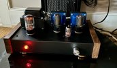
The resultant amp, my first 6V6 amp, is dead quiet and I've just started to listen to it, feeding with phono and CD sources through my Fisher 400 CX-2 pre-amp. As advertised, this is a very pleasant amp to listen to and I have it playing through my Cornwall I's right now. Haven't done final measurements, but sounds fairly rich in even-order harmonics and should put out something like 4-5 watts per channel. Will be interesting to compare to my Blueglow/Kegger KT-88 SEUL, which is considerably more powerful.

A quick sketch of the amp:

1. 6V6GT's into a pair of Edcore 5K primary 8 ohm secondary 10W UL SE transformers (kinda cute to look at at about 2-1/2 x 2 inches).
2. Absolutely no feedback of any kind, NFB, Schade, or other
3. Cathode biased "Optimized operation" of the 6V6's based on a fairly detailed study that Matt did for that tube and published on DIY audio.
4. Driven by his "universal pre-amp" using, in this case, a 12AU7. He says the pre-amp is capable of using a number of 12A_7 tubes, including 12AT7 and 12AX7. I will do some tube rolling once I get a baseline sound in my head from the amp.
5. Instead of a miniature EZ80 rectifier, I used a 5AR4/GZ34 set up since this was possible with the Hammond 273CZX PT I used. I like the 5AR4 tube (easy start), but I had to dissipate a few more electrons as heat than the original design by sizing the main dropping resistor at 750 ohms, vs. 350 in the design set up. This gets the 6V6 voltages in line with Matt's optimized design for the 6V6. The amp can also use other tubes such as well (see his web post on the amp).
6. The design calls for separate RC final filter stages for each channel for max channel separation. Matt feels this provides a better, more expanded sound stage and I'll be listening for this. The filter caps for the OP tube plate supply and the 12AU7 B+ are located at the point of use, spreading them around the chassis underneath. All the filter caps are 450V rating.
7. Initial tube complement: two Sylvania 6V6GT/G beam tetrode output tubes, TAD 12AU7, and GE-labeled Mullard 5AR4/GZ34.
8. Like the Fisher clone, I went for a little more compact design using a 12x8" Hammond steel chassis with the walnut sides, 2" deep. Was a little snug, but it all fit nicely.
Very pleased with it so far and will post a bit later on measurements, some build notes, etc.

Dave
IMG_3231.jpg
IMG_3194.jpg

IMG_3208.jpg
 
Register to hide this ad
Maybe consider a 5V4. Should be more than up to the task and they cost less than a 5AR4. Similar slow-start performance too.
 
Yep, it would. The B+ current draw is about 100mA, which the 5V4G would easily handle, and it has the heated cathode with some added voltage drop. I tried a 5U4GA to get some more drop (way oversize for the current draw), but as a direct heated rectifier the voltage came up quite fast to right at the 450V rating on the first filter cap with my 650VCT power transformer, so I was a little shy of that. I was going to need a pretty large dropping resistor anyway, so I decided to stick with the 5AR4 for now.

If heat build up becomes an issue with the 750 ohm power resistor in place, I may just go to the 5U4 and reduce the size of the dropping resistor and go to a 500V first filter cap. I perforated the bottom plate pretty well, but haven't put any 'flow through' vent holes in the top. The amp doesn't really seem to be building up a lot of heat, but I'm keeping an eye on it. The cathode resistors don't really generate too much heat.
 
Especially curious to hear your impressions of the dampening ability of the amp to control your woofers given that there is no feedback other than the UL tap itself.
 
I built this same amp. It has morphed into somthign else over a year or so since it was finished. I thought it sounded very nice as is, but I built it with mods in mind. First up was conversion to 6L6G. Cathode resistor swap and a bit more B+ did the trick. Next, and most recently, I added some negative feedback. About -7db and it did make a notable difference. Clean clear, punchy bass even driven as far as my preamp can muster (I don't know what that is in watts). The NFB lowered my drive a bit too much with the 6SN7. I swapped in a 6SL7 and I like the improvement. It is playing right now, Amazon music Government Mule station, and it's jamming!

On the bench it's about 5.5W. After adding the feedback I was seeing about .7% THD at 1W, but it was a very rough measure using my FFT scope display. I picked up a working HP 333A last week and the amp will go back on the bench for a better distortion measurement and a look at the voltages after the 6SL7 swap this weekend.

Enjoy. Nice build, looks great.

Edit. I actually built the Lacewood 2, but they are pretty similar.
 
Last edited:
Looks nice and I look forward to you listening impressions. I will have a closer look soon with the intent to build my own. I have always enjoyed your post and projects. Thanks for sharing.

Just my pet peave for project schematics. I really would like to ban the notion of “B+”. Why not call it what it is in volts? In this case you are good by providing the PS that shows 300Vdc going to the marked “B+” in the schematic, but so often it does not.
 
we're dealing with vacuum tubes, a grossly obsolete technology. B+ comes from an even earlier time, when radios ran on battery power. A was filament, B was plate, and C, if it had it, was a bias supply. Why only B stuck around I have no idea, but thats what it is. The idea of getting tube nomenclature to modernize is a bit of a lost cause at this point.
 
Yeah, B+. I have restored and own a 1950's Zenith Transoceanic 'portable' tube shortwave receiver and it actually has a 90V B battery powering the plates of those tubes. Also, an A battery for the heaters of same. No C battery in this one. Our UK friends call it the HT (High Tension) supply, or you could just say "high voltage" and, as you say, call out the target voltage. Let's just call it 'traditional language' or perhaps a little bit of nostalgia for tube stuff. And thanks also, spantou01, for the kind words!

Kidmoe, I have to admit I'm a little light in understanding of amplifier damping factors; determining, interpreting, or using them. I expect that the DF is pretty low for this amp. What I can say so far is that the bass sounds good for a 4W amp with a set of output transformers that are rated (by Edcor) 30Hz-15kHz. Seems tight with the 400 CX-2 bass set to neutral and the loudness on at relatively low volume.

Part of my informal bass test is listening to Scott Lafaro's bass playing (live) in the Bill Evans Trio and it sounds deep, realistic, nuanced and non-flabby. More to come on that. I don't really listen to bass-heavy, need a sub-woofer type music, but will check it out with, say, Steely Dan "Two Against Nature" with some deep bass throughout and see how that sounds. We're early in the process. The Cornwalls are quite sensitive (100db+) and perhaps this is an significant factor, and I recall that their impedance curve is pretty flat at low end, but I'll need to check that out. Interesting question!

SS904, I looked at the Lacewood amps as well with interest, particularly V 2.0, as it was built with Matt's learnings from his 6V6 optimization work, but decided on the Marblewood design for a first try with the 6V6. Interesting set of mods you have done!

By the way, the sound stage for what I've listened to so far is quite open and pretty deep--not forward at all, but we'll see how that goes with different sources and recordings.

Fun stuff! I'll be alternating for a while between this one, the KT-88 SEUL, and the push-pull SA-100 clone.

Dave
 
damping factor is just speaker impedance divided by amp output impedance. High output impedance = low damping factor. Tube amps don't have output impedance numbers like solid state amps anyway, and the less feedback the worse that figure gets. Pentodes with low or no feedback are especially bad about it. Can measure it by changing loading on the amp and watching how the output voltage changes. If its loaded for 8 ohms for example, set it for say 1 volt of output and change the loading to 4 ohms and see how much the voltage drops. Some math from there will tell you what the output impedance is. Off the top of my head I don't remember what it is but its nothing super involved.
 
Nice clean build. I was thinking of building one of these amps since I have a bag full of 6v6's and a few 6SN7's. But I'm going to build the 6L6 amp.
It's more versatile when it comes to driver and power tubes.
I built the Cascade universal preamp. It sounds a lot better than you think k it would, and it can use a variety of tubes also.
.
 
Last edited:
Back from some travel. As promised, a couple of notes/thoughts on the build for anyone who may want to take this one on, first on grounding and noise control; always a priority, especially in single-ended amps.

In the original build, Matt takes considerable pains on the grounding scheme, using a large AWG bus between the power supply and an aluminum partition between the PS and the audio sections. He has a interesting treatise on his website on grounding, which is worth a read. He used the partition for mounting the filter choke as well.

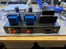
Knowing all that, I decided to follow my own approach which has proved successful, and it did in this case as well. I didn't use a solid wire bus, although this also adds convenience as a solid ground point for filter caps, etc--reducing the number of tie points needed. As seen in the above pic, I mounted a single tie point on the power supply end where the HV center tap connected. To this, I ran a series ground wire from the initial 47uF and 100uF filter caps, and a separate ground lead for each audio channel. There is no chassis connection at the power supply end.

The audio grounds followed a "back end to front end" sequence, first to the 100uF filter caps for the 6V6 B+ and the output transformer common leads, then to the 6V6 ground points (cathode resistor, grid resistor, and 470uF bypass cap), thence to the 12AU7 33uF B+ filter cap ground for that channel as well as the 1.2K||47uF from the cathode. After that, on to the only signal chassis ground point connection by the inputs of the 12AU7 driver using ground tabs and serrated washers with the powder coating carefully removed.

To this single point, I connected the grounds from the 100K audio taper level control pot and the braid from the coax signal leads from the RCA input jacks. The input jacks were isolated from the chassis and the braid from the input coax connected to these as well.

To bring the signal from the input jacks on the back panel to the level control on the front panel, I used Mogami dual-lead microphone cable. This is very well made cable with excellent copper braid shielding. It is fairly stiff, so once mounted doesn't need cable clamps or such to be secure in place and is run close to the chassis opposite the power supply side.

I did not use the partition, as I figured the electro-magnetic isolation from the power supply wasn't needed as much for a power amp as compared to say, a pre-amp (where I did use careful partitioning). I also mounted the filter choke directly to the chassis and its vertical height allows it to just fit flush with the chassis bottom plate, so I didn't need the partition for mounting the choke.

The Hammond chassis I used is steel, which is less effective than aluminum for managing eddy current noise from the power transformer. However, the laminates from the PT, the filter choke, and the output transformers are all mounted in different planes to avoid magnetic coupling. I suspect that mounting the filter caps for the output tubes and driver near their use point helped, but that is speculation.

It's worthwhile noting that I used the IEC three-prong AC inlet (integrated slow blow fuse) with a hard line ground point to the chassis near the inlet socket. I have not experienced any ground loops with my other equipment with this set up.

One final thought: Matt mentions in comments about other builds that he does not ground the common side of his output transformers, believing it to be unnecessary for single-ended amps, if I recall. I did run the signal ground to the common transformer lead, mainly because I always do and this is how all factory builds seem to be.

The result, as I mentioned above, is a dead quiet amp, and by that I mean hearing no hum/buzz or hiss whatever with my ear against my Cornwalls at any setting of the level pot.

I wanted to provide this level of detail for consideration of potential builders, since hum and noise seems to plague single-ended amp builds, as they don't have the inherent noise cancelling properties of push-pull circuits. The approach in the original build works as well, but mine is a bit simpler to implement, at least for me.

A few more build thoughts later.

Dave
 
The amps I've seen that do not ground the speaker side are generally AA5 setups where the audio transformer is also providing isolation from mains. Those also have no GNFB so it doesn't really matter. Anything with a global loop will require the speaker side to be grounded.
 
I grounded my Lacewood build. No difference in sound that I could detect. I was having problems measuring output power. I asked about it here. It was quickly pointed out the ungrounded secondary was the cause. Also noted was the potential safety concerns if a transformer were to fail.
 
I use that same mic cable a lot. It can be more difficult with short runs if it needs to be bent, but it works very well. I've started gathering parts for the
6L6 Spalted Alder amp. I have various 6L6's and a bag full of Tung Sol 5881's along with some KT-77's.
First I considered the 6V6 amp, but liked the idea of trying different power tubes along with using 6SL7's and 6SN7's. I have some of each and a few of the Russian versions of the 6SL7.
 
I see the pictures now. Nice clean build. I used the same OPT's in a sweep tube amp build. They sound pretty good. Some have posted the 15w version is supposedly a better OPT. I guess it tests better.
But the 10w version sounded just fine to me though.
 
Last edited:
Back
Top Bottom