Further information on this build.
First, just a couple of comments on components beyond that already shared. The 0.47uF coupler film caps are CDE 930 series metallized polypropylene construction with tinned copper leads. I have not used these before and decided to try them as an alternative to my usual Illinois Capacitor MPW series metallized polypropylene caps.
The electrolytic bypass capacitors for the 6V6 and the 12AU7 cathodes are Nichicon audio grade caps.
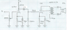
Interestingly, the Marblewood design doesn't use grid stopper resistors for the 12AU7 driver. They are shown (10K) in his 'universal pre-amp' design and I wondered at this, but didn't put them in here. I will do so if there seem to be any related operating problems (such as RF intrusion or other instability). (Thoughts, anyone?....)
OPERATING VOLTAGES
The web description has relatively little information on expected operating voltages, so I'm sharing what I measured once I had the amp set up the way I wanted, mainly through adjusting what the original build shows as "Rd," the main B+ dropping resistor after the rectifier tube. I used a Hammond 273CZ power transformer I had on hand for the build with different specs than the original build shown on line and a 5AR4 rectifier. This PT is 650 VAC 173mA center tapped for the high voltage section with a 6.3V center tapped heater winding (CT unused here) and a 5V heater winding for the rectifier tube.
As mentioned, I ended up using Rd value of 750 ohms (743 ohms measured) to obtain operating voltages downstream for the 6V6's close to the "optimized" conditions used in the original build, based on Matt's detailed study of 6V6 operation and use of the specified Edcor output transformers.
The indicator lamp is a 6V 50mA miniature bulb powered off the 6.3VAC heater circuit and inserted in a fixture originally containing an NE2 neon lamp.
These are the measured voltages from this set up:
AC Line voltage: 120VAC, 0.62amp idle current
B+ voltages: 394VDC post 5AR4; 323VDC post "Rd" (71VDC drop at 743 Ohms yields 95mA total current draw and 6.8W dissipation across the resistor); 312V post filter choke; 303V at output transformers; 301V at 12AU7 plate supplies.
6V6 voltages: 294VDC at plates; 299V at screen grids; 17.6V and 18.1V at cathodes. This gives net voltages of 276VDC on the plates and 280VDC on the screens (by subtracting cathode voltages).
12AU7 voltages: 86.6/82.7 VDC plates; 2.6 VDC at both cathodes.
6V6 calculated current draw and dissipation (392 ohm cathode resistors): 45-46mA cathode current; assuming 5mA screen current draw, would put plate dissipation around 11.0 to 11.3W, or 92-94% of maximum data sheet value of 12W. High percentages would not seem to be unusual for a cathode bias pentode/beam tetrode design as this one is, particularly with UL screen taps, based on my limited experience.
At 276VDC, the plate voltages are right on what Matt describes as an optimized level of performance for the 6V6 in his paper.
After considerable time running, I'm not noticing excessive heat build up. I was wondering about this when I realized that the way I mounted the 'lay down' power transformer, there is a gap around the bottom bell because of the need to enlarge the cut out due the taper of the bottom bell (through which all the wires come in two holes). With the power transformer mounted slightly off the chassis by the laminate nuts, there is a natural 'chimney' for heat to flow up through the holes in the bottom plate, around the big dropping resistor (particularly) and out around the PT. So, I may have inadvertently prevented excessive under chassis build up this way without vent holes in the chassis top. Without this, some ventilation holes in the top are probably a good idea.
By the way, there is zero mechanical noise I can hear from the power transformer in this build. At 95mA B+ current and low demand on the 6.3V winding with only three tubes and the lamp, the transformer isn't stressed at all and runs pretty cool.
Further listening experience continues very positive as the amp plays in. After a while, I'll probably try rolling different brands of 12AU7 driver, or perhaps other types that this pre can accept, according to Matt, such as 12AX7 and 12AT7.
Dave
First, just a couple of comments on components beyond that already shared. The 0.47uF coupler film caps are CDE 930 series metallized polypropylene construction with tinned copper leads. I have not used these before and decided to try them as an alternative to my usual Illinois Capacitor MPW series metallized polypropylene caps.
The electrolytic bypass capacitors for the 6V6 and the 12AU7 cathodes are Nichicon audio grade caps.
Interestingly, the Marblewood design doesn't use grid stopper resistors for the 12AU7 driver. They are shown (10K) in his 'universal pre-amp' design and I wondered at this, but didn't put them in here. I will do so if there seem to be any related operating problems (such as RF intrusion or other instability). (Thoughts, anyone?....)
OPERATING VOLTAGES
The web description has relatively little information on expected operating voltages, so I'm sharing what I measured once I had the amp set up the way I wanted, mainly through adjusting what the original build shows as "Rd," the main B+ dropping resistor after the rectifier tube. I used a Hammond 273CZ power transformer I had on hand for the build with different specs than the original build shown on line and a 5AR4 rectifier. This PT is 650 VAC 173mA center tapped for the high voltage section with a 6.3V center tapped heater winding (CT unused here) and a 5V heater winding for the rectifier tube.
As mentioned, I ended up using Rd value of 750 ohms (743 ohms measured) to obtain operating voltages downstream for the 6V6's close to the "optimized" conditions used in the original build, based on Matt's detailed study of 6V6 operation and use of the specified Edcor output transformers.
The indicator lamp is a 6V 50mA miniature bulb powered off the 6.3VAC heater circuit and inserted in a fixture originally containing an NE2 neon lamp.
These are the measured voltages from this set up:
AC Line voltage: 120VAC, 0.62amp idle current
B+ voltages: 394VDC post 5AR4; 323VDC post "Rd" (71VDC drop at 743 Ohms yields 95mA total current draw and 6.8W dissipation across the resistor); 312V post filter choke; 303V at output transformers; 301V at 12AU7 plate supplies.
6V6 voltages: 294VDC at plates; 299V at screen grids; 17.6V and 18.1V at cathodes. This gives net voltages of 276VDC on the plates and 280VDC on the screens (by subtracting cathode voltages).
12AU7 voltages: 86.6/82.7 VDC plates; 2.6 VDC at both cathodes.
6V6 calculated current draw and dissipation (392 ohm cathode resistors): 45-46mA cathode current; assuming 5mA screen current draw, would put plate dissipation around 11.0 to 11.3W, or 92-94% of maximum data sheet value of 12W. High percentages would not seem to be unusual for a cathode bias pentode/beam tetrode design as this one is, particularly with UL screen taps, based on my limited experience.
At 276VDC, the plate voltages are right on what Matt describes as an optimized level of performance for the 6V6 in his paper.
After considerable time running, I'm not noticing excessive heat build up. I was wondering about this when I realized that the way I mounted the 'lay down' power transformer, there is a gap around the bottom bell because of the need to enlarge the cut out due the taper of the bottom bell (through which all the wires come in two holes). With the power transformer mounted slightly off the chassis by the laminate nuts, there is a natural 'chimney' for heat to flow up through the holes in the bottom plate, around the big dropping resistor (particularly) and out around the PT. So, I may have inadvertently prevented excessive under chassis build up this way without vent holes in the chassis top. Without this, some ventilation holes in the top are probably a good idea.
By the way, there is zero mechanical noise I can hear from the power transformer in this build. At 95mA B+ current and low demand on the 6.3V winding with only three tubes and the lamp, the transformer isn't stressed at all and runs pretty cool.
Further listening experience continues very positive as the amp plays in. After a while, I'll probably try rolling different brands of 12AU7 driver, or perhaps other types that this pre can accept, according to Matt, such as 12AX7 and 12AT7.
Dave