• The move to the new server is done. There are some software and database maintenance updates in process. This has us passing the hat around to help out. We appreciate any donations. Seriously, even a dollar helps. The payment page may be found here - https://www.audiokarma.org/support.html

CA-1000...Lots of Help...

I got the function board back in with nice clean shines switches, did a test and still lower output on the left side. I found a thread where a guy had a similar problem and so I started measuring voltages at different points to see where the issue might be.

On the tone control board is where the “mode switch” is with the input wires (white) coming from the function board and the signal leaves the mode switch to go to the volume board via the orange covered wires. I have 0.378 volts on both sides through the white covered wires from the function board and on the orange wires I have 0.378 on the right and 0.318 on the left!

Tomorrow I’ll be removing the tone control board and mode switch…since I am now and expert switch remover and cleaner, yeah right!!!
 

Attachments

  • 61013567-CD88-4909-B6D5-12DC9F61196F.jpeg
    61013567-CD88-4909-B6D5-12DC9F61196F.jpeg
    92.7 KB · Views: 18
I've took out the tone control board, removed and cleaned the mode switch and even switched out the 220ohm fusister that read 449ohm. After reassembly, I took measurements with the same 1k tone generator and all seemed as it should with .379vac on both the left and right sides. I listened to both sides of a record then the left channel kind of died out. Using my test tone again, I took out my volt meter and confirmed the left channel was lower again and even used a db meter at the speaker that showed the left channel was 5 db softer.

What is weird is that I was getting voltages that were really jumpy, even coming off the function board. Jumpy like I wasn't getting a good connection with the voltmeter probes. Could this be caps going bad? or Transistors? It seemed ok until the amp started getting really warm. Not like overheating just warm after playing for 20-30mins. This is both class A and Class AB.
 
I've been playing the amp and it sounds really good. Still a slight bit of lower output in the left channel.

I could really hear the difference when switching the Mode switch from STEREO NORM to REV and hear the louder right channel jump to the left. So I spent a while testing transistor collector voltages (based on another AK thread) and went back to testing with a 1k test tone and discovered that the imbalance is throughout the system from the volume board. I measured the resistance between the left and right channels on the volume out and there it is...the resistance is off between the left and right channels.

Options? I have already squirted with deoxit D5. Maybe I should try Deoxit fader lube?

I realize a new 4 gang pot is probably unobtanium. Are there other amps that use a 250k linear and 100k audio pot that I could salvage one from? Understanding that it may not be any better...

What about dismantling and cleaning/repairing?
 
The volume/balance pot has reasonable access for spraying lube/cleaner.
Suggest try using a CDP or ipod/phone into AUX, same problem should exist
if it is the vol/balance pot. You thought that the issue was temperature
related which would rule out the vol/balance pot.

With amp powered off/unplugged, volume set to normal/faulty listening level
measure the resistance between the left IN/OUT wires on the volume board.
Repeat for the right channel. They should be the same, +/-20% worst case
hopefully less that +/-10%

upload_2022-1-26_19-29-49.png
 
The volume/balance pot has reasonable access for spraying lube/cleaner.
Suggest try using a CDP or ipod/phone into AUX, same problem should exist
if it is the vol/balance pot. You thought that the issue was temperature
related which would rule out the vol/balance pot.

With amp powered off/unplugged, volume set to normal/faulty listening level
measure the resistance between the left IN/OUT wires on the volume board.
Repeat for the right channel. They should be the same, +/-20% worst case
hopefully less that +/-10%

View attachment 2464484

Measuring between in and out both left and right as you suggest seems to be fine, very close. Where I am seeing the difference in resistance between the left and right on the output. There is a 10%+ difference between white to black and red to black on the output coming from the volume board. It is worse lower in the volume range.

EDIT: And, I did run a 1k test tone through the AUX input. I had 1.7 or so vac on both channels coming off the function board, to the tone board/mode switch, then to the input of the volume board (orange covered leads). Then coming off the volume board (brown covered leads) the signal was much less (of course) and unbalanced e.g., left - 0.16vac, right- 0.23vac ( I may have the exact numbers off but it was that kind of range).

The imbalance continued to the inputs and outputs of the main boards.

That's what led me to checking the resistance between the right and left channels coming off the volume board.

I hope that makes sense.

The temperature thing...yeah I shouldn't try to figure this stuff out late at night...
 
Last edited:
  • Like
Reactions: mbz
There is a 10%+ difference between white to black and red to black on the output coming from the volume board.
The black wires are ground wires, not part of the audio path which is the White(left ch) in/out and Red(Right ch) in/out wires

I did run a 1k test tone through the AUX input. I had 1.7 or so vac on both channels coming off the function board, to the tone board/mode switch, then to the input of the volume board (orange covered leads). Then coming off the volume board (brown covered leads) the signal was much less (of course) and unbalanced e.g., left - 0.16vac, right- 0.23vac
Suggest reflow the 4 sets of wires on the tone board, ie, red and white wires in white/red/brown/orange wrap and the corresponding wires on the volume board. Also inspect/reflow solder connections on vol/balance pot. Give vol and balance a good spray.
 
Will do...Need to wait 'til store that sells Fader lube opens in an hour or so.

Here is what I am measuring. It seems as the resistance though the pot (gang) that controls the left channel does not match the the pot (gang) that controls the right channel. I understand that the black doesn't have signal but it is a reference.

At 1 on volume:
White to blue: 433ohms
Red to blue: 517ohms

At 3 on volume:
White to blue: 4.82k
Red to blue: 5.23k
 

Attachments

  • Volume Board_LI.jpg
    Volume Board_LI.jpg
    109.5 KB · Views: 6
With amp powered off/unplugged, switches in normal positions, ie, MODE=STEREO, measure resistance between LI pin on tone board (white wrap) and LO wire(Orange wrap) repeat for RI and RO wires, expect less than 1 ohm.
 
With amp powered off/unplugged, switches in normal positions, ie, MODE=STEREO, measure resistance between LI pin on tone board (white wrap) and LO wire(Orange wrap) repeat for RI and RO wires, expect less than 1 ohm.
Yes, less than 1 ohm. When I first did it I got a reading of 9.9k. I then moved the switch back and forth to make sure I had it in the right spot. I cleaned the volume pot really well with the green Deoxit Fader lube and still about 10% off.

I put the front face plate back on and then powered it up...got a buzz in the left channel and now no click or even the pilot light is dark. Ugh!
 
I put the front face plate back on and then powered it up...got a buzz in the left channel and now no click or even the pilot light is dark
Would point to main fuse at rear, check if blown. Should also check the 2 glass fuses on the power amp boards.
 
Go with 4A, the 5A is more for full/rated power.
Need to work out why fuse blew, possibly a problem with the left channel power amp since buzz. Are power amp fuses ok?
Do you have a dim bulb tester? Do you know how to diode test the main/output transistors?
 
Go with 4A, the 5A is more for full/rated power.
Need to work out why fuse blew, possibly a problem with the left channel power amp since buzz. Are power amp fuses ok?
Do you have a dim bulb tester? Do you know how to diode test the main/output transistors?

Yes, left power amp fuses are ok. I do not know how to diode test the main/output transistors...but I feel like I am going to learn. I have the parts for a DBT that I just need to put together.
 
Wise to build the DBT rather than risk of doing further damage.
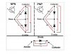
Nice graphic from markthefixer on diode testing, use diode function on MMDiodeTest.JPG

Try testing the output transistor in situ, see tabs on component side, looking for a c-e short, maybe b-e
upload_2022-1-27_10-33-23.png
 
Wise to build the DBT rather than risk of doing further damage.
Nice graphic from markthefixer on diode testing, use diode function on MMView attachment 2465049

Try testing the output transistor in situ, see tabs on component side, looking for a c-e short, maybe b-e
View attachment 2465062
I'll get on that...

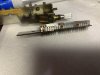
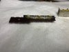
In the meantime, I looked closely at the output board and the 4.7k resistors R627 and R628 looked a little funky, I pulled on leg to test and they are both open! There's a start!

Now, why did that resistor fail? Do they just fail or does something cause them to fail?
 
And, I have continuity between C-E on both transistors...that means their done, right? I compared to the right side and no continuity.
 
Back
Top Bottom