• The move to the new server is done. There are some software and database maintenance updates in process. This has us passing the hat around to help out. We appreciate any donations. Seriously, even a dollar helps. The payment page may be found here - https://www.audiokarma.org/support.html

CA-1000 Rebuild Issues

The operations switch performs 2 functions, 1) selection of transformer secondary
windings for unregulated supply,uses the black snap action switches. Checking the
voltages at power amp fuses (to GND) would confirm all in order.

Second function is a shorting function, ie,
In NORMAL, Pins B and C are connected/shorted
In CLASS A, Pins A, S and C are connected

Previous measurements suggests slide switch is ok.
B&C 0.4 Ohms
B&S 474 Ohms
C&S 474 Ohms
A&B 110 Ohms
A&C 110 Ohms
A&S 584 Ohms

Have you changed the bias transistor? Typically KSC1815 is used as a replacement
with the round face connected to the heatsink
 
Good Day,

I had replaced the snap switches, and the two TR606 to KSC1815
I pulled and checked them (606) on my transistor tester. Tested OK.

Reading 52.3 Vdc at the fuses. Shouldn’t it be 50 Vdc?

I tested the shorting function in A/AB Switch. Tested OK.
I measured the resistance on both settings and found 0.4 - 0.8 Ohms
I cleaned and lubricated the block connectors at the Function Board.
The resistance dropped to 0.1 - 0.3 Ohms

I let the amp run over 5 minutes (off the DBT) then I adjusted the Primary Stage to 15 V
Set theMid-Point Potential Adjustment to 0 V.

On the Idle Adjustments, not so lucky.

A/B Left Channel .047 V
Right Channel .018V Turning the trimmer in either direction doesn’t increase or decrease the voltage.
A Left Channel .09 V
Right Channel .09V

I’m going to remove the .018V trimmer test it, and probably just try another.
We’re getting real close!
 
Yes. But is there a known reason why R633,4 read 0.7 rather than 0.47?
I bought new replacements because I thought they were out of range.
But the new ones measure the same 0.7.
 
Yes. But is there a known reason why R633,4 read 0.7 rather than 0.47?
I bought new replacements because I thought they were out of range.
But the new ones measure the same 0.7.
Lots of equipment doesn't reliably measure below 1ohm.
 
voltage at point/wire C is (still?) low at 0.7v, need about 1.2vdc. This voltage should respond to VR adjustment.
+50 (wire) voltage ok. Possibly some leakage/additional current flow on that +50V regulated rail, eg, C609 leakage???
Check voltages at +50, pin C and S all to GND and compare with working left channel
 
Yes.. You forgot to subtract your test leads resistance..:D
Hello Avionic,
Happy to hear from you. Thanks for clearing up my question on the .47 resistor measurement.
I had never come up against that issue before, and you know I'm far from being a savant on audio electronics.

You have always been extremely helpful and patient dealing with issues (without sarcasm) that I and others have posted on AK.
Your help is Priceless.
Thanks
 
I hoped that I would have better news, but I don't.
Connected the leads to check the Vdc at point C on both channels. Flipped the switch and the relay clicked on.
Let it run a few minutes before logging the voltage on point C. Suddenly the relay clicked off the on and off again.
Then moments later R621(right channel) went up in smoke. :eek:

Before she blew, the voltages on point C were fluctuating between 2.1/2.5 Vdc.
Strange, because I didn't touch anything since I said I felt we were "real close".
I know you must be tired of hearing me say this, any thoughts before pull the board off the heat sink to replace the resistor
and start looking for something else that might have fried.
 
Have you pulled and checked all of the resistors on the amp boards? My knowledge is extremely limited, but I'll say that on the CA-2000, I found many resistors with drifted values or fully open on the driver board that was having issues. Perhaps at some time in the past the amp was run in class A extensively and the heat cooked some of the resistors. I was able to get my amp going after replacing about a dozen bad resistors on each amp board. I am still having issues with meters though.

It's a double edged sword doing extensive parts replacement on this gear. Lots of opportunity to make a mistake and not enough knowledge to easily find it if you do. Without the gracious assistance of some of the folks in this forum, I'd have never been able to figure out some of the issues with my gear over the years.
 
R621(right channel) went up in smoke. :eek:

Before she blew, the voltages on point C were fluctuating between 2.1/2.5 Vdc.
bugga, now point C is higher than expected 1.2Vdc. Possibly TR605,4 are going intermittent blocking TR606, so TR606 is toggling between conducting and non-conducting and point C voltage bounces around. For R621 to blow requires better than 25mA, into the base of TR609...

Previously R625,6 smoked pointing to abnormal TR609e, TR610e voltages however the difference should be set to 1.2-1.8V by D607, TR611be and TR612be. Smoked R625,6 points to a break in this path R627, TR611, R633,4, TR612, R628. You've already resistance checked these resistors.

Two suggestions forward, replace TR604,5 2SC1124ebc with KSC2690ecb or possibly TTC004Becb. This is a long shot based on 0.7, 2.x voltages at point C. Other suggestion is to pull TR609, 610, 611, 612 and connect a 1N4148 with appropriate orientation between b,e of these transistors then DBT power up then full power, see if point C normalizes, possibly one of these transistors is failing open under load (more current than your tester can provide).

Certainly listen to suggestions from others.
 
Have you pulled and checked all of the resistors on the amp boards? My knowledge is extremely limited, but I'll say that on the CA-2000, I found many resistors with drifted values or fully open on the driver board that was having issues. Perhaps at some time in the past the amp was run in class A extensively and the heat cooked some of the resistors. I was able to get my amp going after replacing about a dozen bad resistors on each amp board. I am still having issues with meters though.

It's a double edged sword doing extensive parts replacement on this gear. Lots of opportunity to make a mistake and not enough knowledge to easily find it if you do. Without the gracious assistance of some of the folks in this forum, I'd have never been able to figure out some of the issues with my gear over the years.

When I rebuilt the boards I check every resistor by pulling one lead before testing. I replaced a few of the fuse resistors, but found the balance to be well within range.
Thanks
 
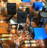
Here's image of the 2690s
I will de-solder them from the board and test them. just for my own satisfaction.
I will then follow your instruction on using the 1N4148 diodes in place of TR609 - 612.

Thank again


IMG_1866.jpeg
 
I missed that you had already replaced TR604,5. Why did you do this, suspect faulty? May help with problem, ie, fault causing additional stress on TR604,5...
EDIT:Maybe add pic of solder side of problematic (R?) power amp board
 
Last edited:
That board had several poor attempts of repair. Seeing that I couldn't test the amp, I thought it best to replace them.
You can see an image of the board on my Thursday 10:13AM post.
 
  • Like
Reactions: mbz
Solder side looks ok, the IN pin appears to have annualized ring, could be lighting, one or two others maybe.
Replacing the transistors with diodes is a rough approximation, would be better to add a series resistor (1-2.2k?)for the NPN's
to simulate transistors Rb?
 
I'd try with the diodes alone then DBT power up, if bulb dims ok then try full power up. The 1N4148 is a 1A item so fairly robust.
Connect diodes, TR609, TR611, base=anode, emitter=cathode. TR610, TR612, emitter=anode, base=cathode.
 
Back
Top Bottom