

You are using an out of date browser. It may not display this or other websites correctly.
You should upgrade or use an alternative browser.
You should upgrade or use an alternative browser.
CA-1000 Rebuild Issues
- Thread starter jandajr
- Start date
Voltages are in the ballpark, R617 voltages should be negative.
Using DBT, try and adjust VR603 to obtain a voltage at "C" of around 1.7-1.9Vdc, the driver and output diodes should conduct, DBT
stable? smoke? If all ok then re-adjust VR603 back to 1V at point C, then power up without DBT and again readjust VR603 for 1.7-19V.
Redo voltage measurements.
Using DBT, try and adjust VR603 to obtain a voltage at "C" of around 1.7-1.9Vdc, the driver and output diodes should conduct, DBT
stable? smoke? If all ok then re-adjust VR603 back to 1V at point C, then power up without DBT and again readjust VR603 for 1.7-19V.
Redo voltage measurements.

jandajr
Active Member
I followed your instruction bringing up "C" then back down again using the dim bulb. No problem.
Took it off the DBT adjusted "C" to 1.8 volts, and started re-checking the measurements
D607 = 0.1
R617 Top = -1.2, Bottom = -1.8
Then the relay clicked off and back on. I shut it down. Didn't see any smoke, just a bit of odor, board was warm.
That's what happened the last time, when it went up in smoke.
Took it off the DBT adjusted "C" to 1.8 volts, and started re-checking the measurements
D607 = 0.1
R617 Top = -1.2, Bottom = -1.8
Then the relay clicked off and back on. I shut it down. Didn't see any smoke, just a bit of odor, board was warm.
That's what happened the last time, when it went up in smoke.
Previously R621,5,6 have all shown signs of stress. "High" current path appears to be from +50 supply through R615,621,625,626 then R622 (Recheck this fusible, may have drifted high). Thinking that possibly TR605 is leaking some -ve voltage at collector/R620.
Check no shorting of transistor legs on TR604.
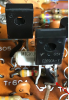
Measure Vdc to GND at R620 as indicated below. Try without DBT, will only have 1-2seconds?

Check no shorting of transistor legs on TR604.
Measure Vdc to GND at R620 as indicated below. Try without DBT, will only have 1-2seconds?
jandajr
Active Member
R622 = 69.7 Ohms
TR604 No shorting (due to the angle of the photo it looks deceptive).
I replaced TR604/05 after the first smoking incident. (that's why the shrink wrap on the collectors are now yellow)
R620 = -1.72 V What should it be reading, I'm getting -1.5 on the left channel.
I'm able to run the amp for a few minutes.
Yesterday the relay started kicking out/in after three plus minutes.
TR604 No shorting (due to the angle of the photo it looks deceptive).
I replaced TR604/05 after the first smoking incident. (that's why the shrink wrap on the collectors are now yellow)
R620 = -1.72 V What should it be reading, I'm getting -1.5 on the left channel.
I'm able to run the amp for a few minutes.
Yesterday the relay started kicking out/in after three plus minutes.
Means the problem is somewhat intermittent. Future voltage measurements need to be performed when the relay is cycling, ie, in the fault state.Yesterday the relay started kicking out/in after three plus minutes.
-1.72V is a little high, expect that it would improve once bias/VR603 is correctly adjusted. Expect -20-50mV's at TP4 then TR612, 610 Vbe's about 1.1-1.3V then small volt drop at R622, sm has -1.25V, I would be overly concerned with -1.5 or -1.7 if the amp biased up correctly.R620 = -1.72 V What should it be reading, I'm getting -1.5 on the left channel.
Redo measurement when relay is cycling.
Is the TP1,2 15V stable or does it bounce around (+/- 0.1V? or more) again during the relay cycling.
Does R636 (10ohms 5W) get warm/hot while relay cycling? Solder connections on R635, L601 ok?
jandajr
Active Member
The amp doesn't just go into protection mode. It goes into a puff of smoke mode.
In the two instances it happened. After two the three minutes of running the amp at full power the relay clicked out back on again, then smoke instantly appeared.
I did find that the soldering on J603 looked a bit suspicious.
One side of the jumper was not laying flat on the board, and the solder point was somewhat flat. Pushed the jumper while heating up pad, and the jumper appeared on the back side. As it should.
Started to check resistors and diodes and transistors.
I found that the resistance between C and S is 0.00 Ohms. Checked R615 474 Ohms (Pulled lead)
I followed the trace from C to B checking each point. R615 is like its' not there!
 "When one light goes out, they all go out"
In the two instances it happened. After two the three minutes of running the amp at full power the relay clicked out back on again, then smoke instantly appeared.
I did find that the soldering on J603 looked a bit suspicious.
One side of the jumper was not laying flat on the board, and the solder point was somewhat flat. Pushed the jumper while heating up pad, and the jumper appeared on the back side. As it should.
Started to check resistors and diodes and transistors.
I found that the resistance between C and S is 0.00 Ohms. Checked R615 474 Ohms (Pulled lead)
I followed the trace from C to B checking each point. R615 is like its' not there!
"When one light goes out, they all go out"Post #4 shows C&S at 474ohms, appears to be intermittent.I found that the resistance between C and S is 0.00 Ohms. Checked R615 474 Ohms (Pulled lead)
I followed the trace from C to B checking each point. R615 is like its' not there!
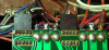
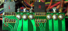
In NORMAL, Pins B and C are connected/shorted
In CLASS A, Pins A, S and C are connected
This is all controlled by the operations slider switch that was dismantled/cleaned. Maybe one of the sliding contacts was damaged during reassembly? Pull the plug on the operations board and recheck C&S resistance
jandajr
Active Member
Both Channels:
In NORMAL, Pins B and C = 474 Ohms
In CLASS A, Pins A, S and C = 0 Ohms
Both Channels:
Disconnected both L&R channel connectors
C&S resistance at solder blobs: Normal = Open
Class A = Connected
Able to run the amp at full power for 5+ minutes.
So I took the following measurements.
Under Full Power:
TP3 = 0.1
TP4 = 0.1
C = 1.70
S = 4.47
TR611 = 0.182
TR612 = 0.256
R617 = Top - 0.62 and Bottom -1.19
D607 = 0.254
In NORMAL, Pins B and C = 474 Ohms
In CLASS A, Pins A, S and C = 0 Ohms
Both Channels:
Disconnected both L&R channel connectors
C&S resistance at solder blobs: Normal = Open
Class A = Connected
Able to run the amp at full power for 5+ minutes.
So I took the following measurements.
Under Full Power:
TP3 = 0.1
TP4 = 0.1
C = 1.70
S = 4.47
TR611 = 0.182
TR612 = 0.256
R617 = Top - 0.62 and Bottom -1.19
D607 = 0.254
Was the operations switch accidently set to class A? Otherwise would need to assume fault in operations slide switch, since no signs of a short/solder bride...I found that the resistance between C and S is 0.00 Ohms. Checked R615 474 Ohms (Pulled lead)
I followed the trace from C to B checking each point. R615 is like its' not there!
Problem is intermittent, you might be able to provoke it by wiggling or putting gentle pressure on the operations switch.
Above voltages are in the ballpark, expect to improve when drivers/outputs reinstalled and bias adj.
Suggest do not reinstall drivers/outputs, no fault has been found, try and provoke the fault any way you can, only use normal operations.
Are you on DBT?I'm not getting any movement on VR603 /VR604 on Both Channels, when I try to set the Idling.
With the diodes in place adjust VR603(Normal) for targeted voltages, ie, adjusting the VR causes movement to these voltages,
- wire/point C, 1.9V
- D607 anode, 1.2...1.3V
- D607 cathode 0.6...0.7V
- TP3 10-100mV
Then check the following are in the ballpark
- TR611emitter/diode cathode -0.6...-0.7V
- D602 cathode -1.2...-1.3V
I thought the left channel was working ok? DBT?
On left, check if point C responds the VR603 adj, target is 1.9V
jandajr
Active Member
I'm not on the DBT
Before I take the measurements you requested (above), here's what I have.
TP1 / TP2 = 15V On both channels.
OUT / E = 0V On both channels.
B Class Idle: Left channel .047V
Right channel Trimmer not responding.
A Class Idle: Left channel Trimmer not responding
Right channel Trimmer not responding.
Will get you the balance of the measurements you requested.
Thanks
Before I take the measurements you requested (above), here's what I have.
TP1 / TP2 = 15V On both channels.
OUT / E = 0V On both channels.
B Class Idle: Left channel .047V
Right channel Trimmer not responding.
A Class Idle: Left channel Trimmer not responding
Right channel Trimmer not responding.
Will get you the balance of the measurements you requested.
Thanks