• The move to the new server is done. There are some software and database maintenance updates in process. This has us passing the hat around to help out. We appreciate any donations. Seriously, even a dollar helps. The payment page may be found here - https://www.audiokarma.org/support.html

Can 5AR4 be substituted with 5R4G variants?

0.9 ohms can't have a lot of inductance. At that point its probably acting more like a cap input supply. Based on the 5ar4 datasheet, I'd expect about 460 vdc with a cap input supply with 430 vac per plate input. Something just doesn't add up, either the AC input is higher than your meter is telling you, or the DC output is lower than your meter is telling you, or the current load is low.

A 10H choke for a choke input supply should give about 350 vdc output for 430 vac input.
 
I used different meter today. My Fluke died about a month ago after only 24 years of faithful service.

Here is what I got:

Primary winding resistance is 1.2-1.3ohm
Secondary winding resistance one tap is 39.7ohm and another is 37.1ohm to grounded center tap.
Secondary AC voltage with rectifier pulled is 428vac each tap to ground.
Secondary AC voltage with rectifier installed and amp idling at 168ma is same - 428vac each anode to ground. (strange or indication of healthy PT reserve?)

All resistances and voltages on my drawing below are as measured with outputs set at 40ma draw (.400v across 10ohm 1% cathode resistors)
122vac from the wall.

Chokes on my drawing are of unknown specs and measured at .7ohm in series.
They are nearly 3x size of the ones that came with organ. Originals were getting hot and were buzzing measured 36ohm in series. As I remember, they lowered voltage slightly below 450v at close to specified output stage load.

Screen grid 100ohm resistors installed but I doubt they play any role here.

I'll be honest, PSUD2 is in Greek to me. I understand how all selected components affect the circuit but there is a lot of gray area for me. I'm not sure how to enter PT data, what capacitor resistance to choose or what choke parameters to enter. It seems like it was meant for engineers. I would probably get it if someone walks me through it. I definitely lack common knowledge here.

My fear is that chokes that would fit the bill here will be so huge that I won't be able to fit them in the chassis. Then what? Dropping resistor/capacitor input?

Thanks for your help, guys!
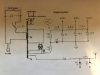
upload_2018-4-2_22-40-3.png
 
Ok so it seems the output stage anodes are fed from 463V rail, and the screen current is from the 400V rail, and you are using a 5AR4 valve. It doesn't look like the chokes are doing much and you could likely leave them out and not notice much change at all.

If you put a choke in as L2 with 5-10H and rated for 160mA then it will have about 100 ohm resistance. The ripple on the output stage will be very low, but you will get some turn on voltage overshoot, and the voltage rails will be about the same if you keep about 338 ohm (choke plus separate resistor).

The 22uF cap will see about 280mA ripple - that could be more than your cap is rated for.
 
Does this data box look right using data in post #22?

IMG_2271.JPG

I played around with choke values and came up with following. Looks like my current setup with the exception of missing dropping resistor that I can't insert right after second choke.

IMG_2272.JPG

I tried inserting different choke values and can't come up with needed voltage.
Can someone review my transformer data selection and confirm that I did not make a mistake there?
Thanks
 
I just tried something.
I increased variac output so transformer gets 122v after CL-80 limiter. That bumped my unloaded voltage to 443vac.
 
You need a bigger choke. More inductance that is. Output voltage should be .9x the AC, rms input of 428V, take a little bit for rectifier drop on top of that, for an LC filter with more than the critical inductance.
cheers,
Douglas
 
exactly, with chokes under 1 ohm DCR, there just can't be all that much inductance going on. At that point its effectively a cap input power supply. Cap input supplies with a full wave rectifier are basically 1.4x the AC voltage input, less losses for the rectifier and losses due to transformer loading. Choke input are 0.9x AC input, less losses. AC measurement would be center tap (ground) to one plate, not end to end.


What does the HV winding produce with it plugged straight into the wall? Use that voltage for calculations if thats how you plan to run the amp. If the heater supply is more than 6.6 vac, consider adding a bucking transformer to the mix to get it closer to the 6.3 vac nominal.
 
That's how I measured it. Center tap to single plate is 428vac with 122vac from the wall with CL-80 installed. Filament voltage is at 6.4vac at that point.
If CL-80 is removed from equation I get 443vac on the plate (rectifier removed) Did not measure filament voltage. I'm sure it's slightly higher.
So, with choke input, the highest voltage that I could possibly achieve would be somewhere around 390vdc, correct? Can I expect decent output stage performance with less then 400v on 7591 plates? If I calculate correctly, they will conduct about 41ma at 16 watts of dissipation. Would that be ok?
 
grindfix it sounds like you are becoming a bit more accustomed to PSUD2. PSUD2 is aimed at being as simple as practical, so some 'workarounds' are often needed to make it work for specific circuits, and for it to adequately indicate what will happen in a real amp.

A mains side thermistor adds some resistance to the primary winding - that resistance can be added to the primary winding resistance of 1.2 ohms to achieve a closer match with what you actually have. Estimating the thermistor resistance when hot becomes your next hurdle.

Similarly is you use a separate resistor in series with a choke then that extra resistance can be added to the choke 'series resistance' value to give a combined resistance equivalent to what you have in practice.

There are numerous other subtleties that people have worked through with PSUD2, and you also need to be careful not to 'believe' in every result. The simulation can't properly model inductors during start-up if the inductance changes a lot. Some extra effort is also required for choke input filtering where the output stage valves may not conduct for tens of seconds - that can be 'modelled' by using a current tap load, and using the 'step' feature to change from an initial loading to a later loading.

With respect to capacitor ESR, sometimes you can get an estimate of ESR from a capacitor datasheet - but leaving the value at the 2 ohm default is unlikely to be a concern for your use.

Ciao, Tim
 
Off topic question; which model is your Fluke and describe ''died''. I am rather savvy with the older Flukes:)

It was Fluke 78 automotive. I believe it got fried with current exceeding 10A through mis-fused tap. Ignition was turned on by accident while meter was in series to battery. Wrong fuse held-up :( I was hoping that it was contact or solder joint inside but did not find any issues.
It was not showing nowhere close to 0ohm with leads touched. It's gone now. Looking for replacement.
 
grindfix it sounds like you are becoming a bit more accustomed to PSUD2. PSUD2 is aimed at being as simple as practical, so some 'workarounds' are often needed to make it work for specific circuits, and for it to adequately indicate what will happen in a real amp.

A mains side thermistor adds some resistance to the primary winding - that resistance can be added to the primary winding resistance of 1.2 ohms to achieve a closer match with what you actually have. Estimating the thermistor resistance when hot becomes your next hurdle.

Similarly is you use a separate resistor in series with a choke then that extra resistance can be added to the choke 'series resistance' value to give a combined resistance equivalent to what you have in practice.

There are numerous other subtleties that people have worked through with PSUD2, and you also need to be careful not to 'believe' in every result. The simulation can't properly model inductors during start-up if the inductance changes a lot. Some extra effort is also required for choke input filtering where the output stage valves may not conduct for tens of seconds - that can be 'modelled' by using a current tap load, and using the 'step' feature to change from an initial loading to a later loading.

With respect to capacitor ESR, sometimes you can get an estimate of ESR from a capacitor datasheet - but leaving the value at the 2 ohm default is unlikely to be a concern for your use.

Ciao, Tim

Tim,

Could you review this screenshot please?
Does it look like useable scenario?
Out of 157ma total load about 147 will be 37 something per output tube. Which is about 15 watts of dissipation.
But that low choke value may produce noise just like original chokes that were designed to handle single channel loads.
From all calculations that I found correct choke should be about 3 henries. If I select that value in psud2 my rail voltage falls into 360v range which is probably way too low for proper output tube operation.
What are my options?
I understand that current limiter will add resistance to the primary but that should not be of huge significance in the end result, should it?
Thanks
 

Attachments

  • IMG_2276.JPG
    IMG_2276.JPG
    114.5 KB · Views: 8
I think you've made a good start!

Unfortunately you are now in a swirl of 'what-if's' and 'what's better'. As you can see, using a full-on choke input will perhaps lower B+ too much.

If it was mine, I'd probably start without a choke and just simply C filter after the rectifier, and use RC to filter and drop screen supply to a safe level. B+ may be a tad high by the datasheet, but that never stopped many a diyer, as long as screen supply is within ratings and valve dissipation is known and has a bit of margin. If you're still a little un-nerved then initially install a CRC filter to bring down B+ a bit more. If hum from screen supply, or output stage, is too much then leave room to retrofit a choke (ie. CLC main filter rather than just C filter), as that will drop supply voltage a bit more.

I'm sure there are lots of other design and construction things in the amp to initially vacillate over :)
 
That is pretty much what I have now.
If my current chokes aren't doing anything my filter is 22uf/330ohm/47uf
CRC filter.
What about trying 5R4GYB?
I may not need resistor or at least not as large.
Also, I can try lowering first cap a bit and see what happens.
Is there a ratio or guideline to keep between plate and screen voltage?

Thanks
 
You may be able to do a cap input and use the original two chokes in place of that 330 resistor. They ought to behave themselves better that way. Basically it would be a CLC at that point vs a CRC.
 
That pretty much confirms your PT is rated for 350-360v of loaded output. If you were to buy one off the shelf you would ask for a 720v center tapped transformer.

It's easy enough to calculate. 425v unloaded x .85 or .8 = a close rating. Then you decide if it can carry the load you need. That's a different problem. Better to know what the original rating data is for it.

So you have a tranny has similar voltage specs to a Dynaco ST-70. Can it give you 200ma? Are you limited to less than that?

That is the problem. I don't know PT ratings. There are no published numbers because it was not commercially available model and was wound specifically for this Hammond organ chassis. At least that was what Trek II (supplier) told me. AO-63 H-100 organ.

I have no idea about 200ma. That would be about 16.5w saturation at 360v, correct? That sounds like it will be running pretty hot. Am I correct?
How would it sound in those conditions?
 
You may be able to do a cap input and use the original two chokes in place of that 330 resistor. They ought to behave themselves better that way. Basically it would be a CLC at that point vs a CRC.

I could try that.
What cap value to use out of 5AR4?
It has to be lower then 22uf I got, but much higher voltage and high ripple rated, right?
 
I think a 5ar4 is rated for 40uf max. It will be dealing with a fair bit of ripple current too. 450v at a minimum, 500v is better.
 
If that PT meets the original specs, then the organ used 400v B+ derived from 1 choke with 40 ohms, don't know the H. But it would be some common choke 5 - 10H. (Although it could also be more like 3-5H. to get to a 400v B+) That is filtered by 40uF. That would put your tubes at @390. The fixed bias looks to be about 20v. The G2 is @ 350v. I don't have data on the tube to say what the current is at that operating point.

... a little editing done on my choke value speculation.

According to schematic First B+ is 450v, Screen is at 400v
And, I was getting 450v with original chokes. They were buzzing, getting warm and did not filter very good.
 
Back
Top Bottom