You are using an out of date browser. It may not display this or other websites correctly.
You should upgrade or use an alternative browser.
You should upgrade or use an alternative browser.
Can 5AR4 be substituted with 5R4G variants?
- Thread starter grindfix
- Start date

YepLoaded has to be with the output tubes in, and hot, not just a quicky reading with no output draw...
Idling around 40ma per output tube
Here are today's test results with another different meter that is supposed to be true RMS.
438vac with all tubes pulled at 122v with CL-80.
444vac without CL-80. Transformer sounds unhappy.
With CL-80
With all tubes installed 423vac, 520 vdc filtered through 22uf/338ohm/47uf gets 463vdc Idling at 40.5ma
Without CL-80
With all tubes installed 432vac, 533vdc Gets 474vdc through 22uf/338ohm/47uf Idling at 41ma
Transformer is humming unhappily without CL-80.
438vac with all tubes pulled at 122v with CL-80.
444vac without CL-80. Transformer sounds unhappy.
With CL-80
With all tubes installed 423vac, 520 vdc filtered through 22uf/338ohm/47uf gets 463vdc Idling at 40.5ma
Without CL-80
With all tubes installed 432vac, 533vdc Gets 474vdc through 22uf/338ohm/47uf Idling at 41ma
Transformer is humming unhappily without CL-80.
PT and OPTs are bolted down to the chassis using original star washered nuts and transformer bolts.
Hum balance pot/circuit is removed.
Filaments are raised with around 25vdc instead.
PT hum is vibrating through the chassis. I did not notice it going through speakers. I'm sure PT wasn't designed to be used with 122vac. That organ is from 60s, correct? Average outlet voltage was probably around 115vac or so.
Hum balance pot/circuit is removed.
Filaments are raised with around 25vdc instead.
PT hum is vibrating through the chassis. I did not notice it going through speakers. I'm sure PT wasn't designed to be used with 122vac. That organ is from 60s, correct? Average outlet voltage was probably around 115vac or so.

trobbins
Super Member
Just some queries to mull over 
Has the PT been removed from original chassis then replaced, or otherwise repositioned?
Do you have a photo of the PT? Does it use the original clamping bolts? Are the bolts going through holes in the transformer core, and are the bolts insulated at one end, and tightened up? How is the transformer mounted to the chassis?
Does the hum vibration reduce when variac is lowered down to 110Vac (no thermistor in circuit)? As mains voltage increases, the magnetising current increases, and the current waveform can show signs of saturation starting to be an influence.
I use a cheap plug-in mains power monitor to check that the magnetising current (no secondary loads) is not abnormally high - as that may indicate an internal shorted turn somewhere.
Has the PT been removed from original chassis then replaced, or otherwise repositioned?
Do you have a photo of the PT? Does it use the original clamping bolts? Are the bolts going through holes in the transformer core, and are the bolts insulated at one end, and tightened up? How is the transformer mounted to the chassis?
Does the hum vibration reduce when variac is lowered down to 110Vac (no thermistor in circuit)? As mains voltage increases, the magnetising current increases, and the current waveform can show signs of saturation starting to be an influence.
I use a cheap plug-in mains power monitor to check that the magnetising current (no secondary loads) is not abnormally high - as that may indicate an internal shorted turn somewhere.
Just some queries to mull over
Has the PT been removed from original chassis then replaced, or otherwise repositioned?
Do you have a photo of the PT? Does it use the original clamping bolts? Are the bolts going through holes in the transformer core, and are the bolts insulated at one end, and tightened up? How is the transformer mounted to the chassis?
Does the hum vibration reduce when variac is lowered down to 110Vac (no thermistor in circuit)? As mains voltage increases, the magnetising current increases, and the current waveform can show signs of saturation starting to be an influence.
I use a cheap plug-in mains power monitor to check that the magnetising current (no secondary loads) is not abnormally high - as that may indicate an internal shorted turn somewhere.
Transformers are bolted using original hardware. PT is a replacement sold by Trek II. I contacted them. They claim that it was wound to replace original transformer but are not willing to give out its specs.
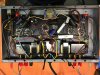
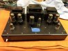
I'm using my own chassis in pictures below.
I will back off variac to 110 without limiter and post results.
Attachments


I agree on underrated cap.
Trek is supplier of Hammond organ replacement parts.
Agree on chokes. As I calculated it needs to be at least 3 henries or higher.
Voltage drops down to 360vdc if I try that in psud2.
Picture of original chokes (that hum and buzz) are on the top of the ones currently installed which not really doing much.
So without the right choke or chokes, even a 5R4 type isn't going to give enough voltage drop to compensate. It might come down 40v-50v if the current is high enough, but still out of range.
You can add a big resistor after the rectifier ahead of the 1L choke to get it down some more, too.
Did you say earlier that you don't know what the H value of the chokes you are using is?
I do not. Original small ECH-1 chokes values are not published. Ones that are installed are of unknown spec. They are out of Wurlitzer organ. That is why sim shows 0.2 henries. Using those values sim looks close voltage and current wise to what is actually happening in amp at idle.
Wurlitzer was dismantled before I got to it. It could have been solid state output filter.Ohhhhhhhh.....
Any info on the Wurlizer?
If your chokes came out of a PS then there is no way they are 200mH. When you read the resistance through them and said .7ohms together in series, that was reading in the circuit, with a capacitor in between, correct? You have to disconnect them for the resistance reading, at least one end of each, and only read one choke at a time.
Measured out of circuit and without cap

If you have a signal generator, a scope, and a selection of capacitors or resistors you can ring out the chokes to figure out their value. The easy way is of course something that just reads them directly.
https://www.wikihow.com/Measure-Inductance
https://www.wikihow.com/Measure-Inductance
Well, you're brave. What you have built is a Kamikaze choke tester.
It was shot in the dark. First timer. Not gonna happen again. Variac and DBT kept me safe.
I have handheld signal generator, scope and handful of caps and resistors. Lets see what I will be able to accomplish.
I really appreciate all your guys inputs!
With @trobbins' help I practiced variety of PS options in PSUD2. I'm sure my understanding of this barely scratches the surface, but I think, I came-up with possible resolution.
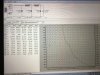
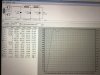
Hammond makes 194G choke for Marshall Plexi amp that is 3H/250mA 79.92ohm. Using pair of those with 47uf cap across between them and 3.3uf cap off rectifier seems to get the voltage in the 415v range at idle. Images below.
My next step is to determine optimal screen voltage to suit lower then stock plate voltage. I read DG's post on screen voltage effect on gain and power. It appears that my next step should be measuring my OPT impedance since that determines optimal output tube load impedance, which can be adjusted by screen supply voltage.
Did I get that right?
How could one achieve that without poking around with different resistor values? Can target screen B+ be calculated if OPT turns ratio/impedance is known?
Hammond makes 194G choke for Marshall Plexi amp that is 3H/250mA 79.92ohm. Using pair of those with 47uf cap across between them and 3.3uf cap off rectifier seems to get the voltage in the 415v range at idle. Images below.
My next step is to determine optimal screen voltage to suit lower then stock plate voltage. I read DG's post on screen voltage effect on gain and power. It appears that my next step should be measuring my OPT impedance since that determines optimal output tube load impedance, which can be adjusted by screen supply voltage.
Did I get that right?
How could one achieve that without poking around with different resistor values? Can target screen B+ be calculated if OPT turns ratio/impedance is known?