• The move to the new server is done. There are some software and database maintenance updates in process. This has us passing the hat around to help out. We appreciate any donations. Seriously, even a dollar helps. The payment page may be found here - https://www.audiokarma.org/support.html

Can you identify a replacement Zener Diode

kaplang

Works for me !
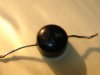
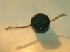
The Zener Diode is from a Sansui Eight Driver board Sansui part # 0310830. I need a replacement but I don't know the value. Any help would be appreciated.

ZD1.jpg

zd2.jpg
 
Register to hide this ad
Are you sure that's a zener? the schematic diagram on the unit is a standard diode, not a Zener symbol...

I wish I could help more, but I gotta point out, that's one weird lookin' diode:yes:...out of curiousity, what warranted a replacement?, I haven't heard much about diodes failing, but I assume something went wrong:scratch2:
 
ZB1 crosses to a ECG5079A, a 20V, 1W zener diode, in my vintage ECG master replacement guide. I didn't downloaded the schematic to see if it makes sense.
 
Thanks ecluser

If you had the data sheet for an ECG5079A. How would you determine if it makes sense? How can you know the value of the ZB1?
 
The service manual calls it a Zener. It tests as open both directions. :no:

well, yeah...uh, "Theres your problem":D

Glad to see someone has information in getting a new one, As i'm not familar with zeners much, and Sansui even less so. One funky diode, neat looking though, I may have seen one like it a while back. I can only assume that modern replacements will probably look more standard.
 
A 20V zener does not make sense. The zener sets up a stable voltage when is then tapped with a trimpot to set the current in the input differential pair. According to the scat, the voltage at the tap is only 2.04V. A 20V zener would make this a damn touchy adjustment, unless I'm looking at this from the wrong angle.

Seems the part number (ZB-1-8) may be providing a clue. I'd suggest that it may be an 8V 500mW zener. The supplied voltage at the B3 bubble is a regulated 46.5V. If the zener was 8V, then the max current in the zener is about 4mA, so a 1/2W zener would be fine.

If one side is functional, it would be a great help to power it up and simply measure the voltage on the cathode of the zener. Mystery solved.
 

Attachments

  • Eight_Input.jpg
    Eight_Input.jpg
    115.1 KB · Views: 56
If VR802 is a 3 kOhms pot, R 810 a 10 kOhms resistor and there is 46.5 V at point 8P, it doesn't make sense to put a 20 V zener at ZD801. The maximum voltage between VR802 and R810 would be 10.7V in the absence of the zener. If you measure a voltage lower than 20 V without zener, there is no justification to put a 20 V zener there, and a 8.2V would be more appropriate.

By the way, ZB-1-8 crosses to a ECG5072A, a 8.2V, 1W zener

But if VR802 is a 30 kOhms pot, it does make sense to use a 20V zener.

From this schematic, I am more inclined to think it is a 8.2V zener.

 
1W? Seems like the zener would be operating on a pretty soggy part of the knee. But then, it's a Sansui.
 
If we consider the voltage divider VR802 and R810, the current in the zener is only 1.1mA, so a 1/2 W zener is more than enough for this application.
 
It is within 10% of the nominal voltage of a 8.2V zener. Considering the very low current in the diode, it is not abnormal to have this low voltage.
 
Back
Top Bottom