• The move to the new server is done. There are some software and database maintenance updates in process. This has us passing the hat around to help out. We appreciate any donations. Seriously, even a dollar helps. The payment page may be found here - https://www.audiokarma.org/support.html

Causes of crazy DC offset but idle current in spec ...?

Julian12345

Active Member
Hey all

Long time reader, first time poster so if this is in the wrong area feel free admins to bump me to elsewhere. Ill learn
I've been dabbling in electronics for years now and am pretty good at finding, sourcing and replacing bad components; caps, transistors and so on.
BUT
I have a few amps on my project bench and one in particular is annoying me.
It's a Nivico 5003 that worked briefly after I bought it then it got smokey. I recapped it very carefully (probs the 20th item I've recapped over the years to no ill effect usually!) as believed it might be perhaps bad filter caps? Anyways, I've recapped, checked trans and appears to test fine on primary and secondary in terms of ohms. The driver transistors got hot and smoked. I replaced them. I found NOS for 2SA537A and for 2SC708A I used equivalent 2N3440 and I have enough stock to replace both types two more times. I haven't replaced 2SC458's yet as I couldn't get the modern equivalents I think they were, BC549 to work despite triple checking the pin out arrangement and orientation (which I checked like 7 times), so I put the 458's back in.

I can see 300mv generally speaking on DC offset and when I play with the trimmers (I know its a bad impression, I do have a dim bulb tho if that helps) I seem to get them down to about 120mv the they hunt all over the place again.. things still to get hot so I return it to the approximate original position (yep also dodgy way of looking at things, I know) and turn off the receiver.

I've replaced the SVT3's with the 3x 1004 I think they were, there's a solution online that shows how to do this so I went ahead because at the time I didn't know how to test SVT3's and one of the legs broke anyways so replaced both.

Idle current seems not spicey, it's low but not spicey.. I think I saw around 4mv

I have a full original service manual out of an old binder that came with the receiver if anyone wants me to take pics.

No idea what to try next.... Feel free to ask for pics

Cheers
Julian
Hobart, AUS.
 
Register to hide this ad
Long tailed pair is no longer a stable matched pair... Differential pair..
 
I can see 300mv generally speaking on DC offset and when I play with the trimmers (I know its a bad impression, I do have a dim bulb tho if that helps) I seem to get them down to about 120mv the they hunt all over the place again.. things still to get hot so I return it to the approximate original position (yep also dodgy way of looking at things, I know) and turn off the receiver.
Dead give away for the differential amplifier circuit. ( see previous post )
Idle current seems not spicey,
Its not a condiment.... :rflmao:

Bias has no bearing on DC offset.
 
Dc offset is the differential pair of transistors. Not matched anymore.
Bias won't affect dc offset.
Try the bias(idle current) between habanaro and ghost pepper,then try jalapeños.
Most of my stuff is at Chipotle and Saracha.
I have some tube gear that's set to
de arbal .
 
Long tailed pair is no longer a stable matched pair... Differential pair..
Oh right, so I should be sourcing NOS 2SC708A?
Dc offset is the differential pair of transistors. Not matched anymore.
Bias won't affect dc offset.
Try the bias(idle current) between habanaro and ghost pepper,then try jalapeños.
Most of my stuff is at Chipotle and Saracha.
I have some tube gear that's set to
de arbal .
Mmm Chipotle :banana:
 
Thanks all for your input! It makes so much sense and now I've learned something about matching transistors... I've found some NOS 708's for reasonable price in Europe.. Ill report back once I install them but expect it'll take about 6 weeks or 6 years for them to arrive.
 
Actually, I dont think your issue with roaming DC offset is being caused by the 708's. I would lean more to the initial transistor 2SC458's which are know to get noisy and cause issues such as this.
This unit (JVC Nivico 5003) doesnt use a differential pair like newer solid state units, but does have the initial amplifier (X401 one channel, and X402 other channel. They are 2SC458LG, and I usually replace them with KSC1845. Matching close is nice, but not as critical as a differential pair.
As a FYI, that unit has a lot of 2SC458's that you may consider replacing if you develop any static, crackling, or popping issues
 
Last edited:
JVC Nivico 5003)
Is this the receiver?
If so, this is capacitor coupled outputs, so no dc-offset!! ( better said, a lot of DC (40 V according schematic)that is blocked by the capacitor)
The trimmers on the board are for bias current and dc-balance (R421/422).

There are no STV-3 in this unit they are thermistors.
 
Last edited:
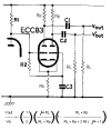
its more of a relic of the tube era, when the circuit looked like this

1699647526742.png

Rk is the "tail" resistor, functionally equivalent to an emitter resistor or a CCS or whatever its got in that spot in a solid state amp. Its "long" because the cathode resistor is a relatively high value to emulate a constant current arrangement. Its imperfect but the bigger you make it, the less signal changes will affect it so it gets you close enough with a cheap, dumb part.

Rarely do you see these used exactly like they are in a solid state amp, but they can be. SS amps use both bases for input, one for the negative feedback, the other for the signal input. Tube amps usually don't for whatever reason, but its certianly possible to do it.


anyway, if this is in fact cap-coupled it won't have offset. Any DC at the output is output coupling cap leakage.

There are two adjustments on most cap coupled units though. One is the DC bias, the other is a balance or centering control. Couple ways to set it if the manual doesn't give instructions but generally you can measure the rail voltage, then set the amp side of the output coupling cap to be 1/2 of the measured rail voltage, or a smidge below. Best method is to use a scope and tweak it for symmetrical clipping but the voltmeter method gets you pretty close.
 
If the tube amp has a negative supply, ie bias supply, the "tail" resistor can be tied to that and the "tail" can be even longer.

Craig
 
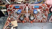
Here's the board and schematic that came with the amp
I did replace the 458's last night with c945 and no change.
 

Attachments

  • 385551787_2009578212737203_6451628268016421437_n.jpg
    385551787_2009578212737203_6451628268016421437_n.jpg
    140.2 KB · Views: 36
  • 385531087_3591954774453360_4423485399006162301_n.jpg
    385531087_3591954774453360_4423485399006162301_n.jpg
    85.9 KB · Views: 34
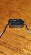
Also these are what came out of the receiver as well, they were mounted on the chassis above what I think are the emitter resisters
 

Attachments

  • 372062903_1767708337004341_8259542276279794266_n.jpg
    372062903_1767708337004341_8259542276279794266_n.jpg
    104.1 KB · Views: 28
Also these are what came out of the receiver as well, they were mounted on the chassis above what I think are the emitter resisters
Thats a diode of some kind. Do they have SDT-20 in print on them ?
 
Last edited:
This may also help, if we ignore the DC side of the conversation and just run the receiver it sounds OK at low volume then distorts badly from half volume onwards while the 708 and 537 replacements get very hot
 
service info here


its a little hard to follow since the output transistors appear to be external from the rest of the board, and it doesn't show it all in one place. This is the driver board though

1699657475089.png

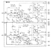
and this is the output stage part of it all

1699657575357.png

looks like fairly conventional quasi-comp single rail cap coupled stuff. Note the +40v spec on the + side of the output coupling cap and the 88v main supply voltage. If that voltage at the cap is way screwed up, the power output will be very limited and it will distort early so make sure that is correct. I got nearly double the output power from a Sherwood by fixing that and it sounded much better.

if I'm not way off here, R422 will be the centering voltage adjustment and R436 is your bias. I don't know what the bias ought to be set to, but it would be measured across one of the 0.5 ohm emitter resistors. If those adjustments are too screwed up it doesn't surprise me that the drivers get hot either.

This also calls for thermistors for bias temperature compensation, not triple diodes like an STV would be. An STV-03 should be 3 diodes in series inside that blob and if you measure it with a diode check function it ought to show about 1.8 volts of drop.
 
service info here


its a little hard to follow since the output transistors appear to be external from the rest of the board, and it doesn't show it all in one place. This is the driver board though

View attachment 3032570

and this is the output stage part of it all

View attachment 3032573

looks like fairly conventional quasi-comp single rail cap coupled stuff. Note the +40v spec on the + side of the output coupling cap and the 88v main supply voltage. If that voltage at the cap is way screwed up, the power output will be very limited and it will distort early so make sure that is correct. I got nearly double the output power from a Sherwood by fixing that and it sounded much better.

if I'm not way off here, R422 will be the centering voltage adjustment and R436 is your bias. I don't know what the bias ought to be set to, but it would be measured across one of the 0.5 ohm emitter resistors. If those adjustments are too screwed up it doesn't surprise me that the drivers get hot either.

This also calls for thermistors for bias temperature compensation, not triple diodes like an STV would be. An STV-03 should be 3 diodes in series inside that blob and if you measure it with a diode check function it ought to show about 1.8 volts of drop
 
Back
Top Bottom