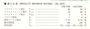
service info here

www.hifiengine.com
its a little hard to follow since the output transistors appear to be external from the rest of the board, and it doesn't show it all in one place. This is the driver board though
View attachment 3032570
and this is the output stage part of it all
View attachment 3032573
looks like fairly conventional quasi-comp single rail cap coupled stuff. Note the +40v spec on the + side of the output coupling cap and the 88v main supply voltage. If that voltage at the cap is way screwed up, the power output will be very limited and it will distort early so make sure that is correct. I got nearly double the output power from a Sherwood by fixing that and it sounded much better.
if I'm not way off here, R422 will be the centering voltage adjustment and R436 is your bias. I don't know what the bias ought to be set to, but it would be measured across one of the 0.5 ohm emitter resistors. If those adjustments are too screwed up it doesn't surprise me that the drivers get hot either.
This also calls for thermistors for bias temperature compensation, not triple diodes like an STV would be. An STV-03 should be 3 diodes in series inside that blob and if you measure it with a diode check function it ought to show about 1.8 volts of drop.



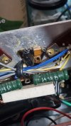

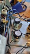
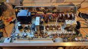
 because I'm so keen to use this receiver - it's been sitting there a while now. I'm at a loss

 ) I still have distortion at half or more volume even with current limiter bypassed