• The move to the new server is done. There are some software and database maintenance updates in process. This has us passing the hat around to help out. We appreciate any donations. Seriously, even a dollar helps. The payment page may be found here - https://www.audiokarma.org/support.html

Causes of crazy DC offset but idle current in spec ...?

Hey @gadget73 , I bought all the stuff to build a dummy load with 4x 100 watt resistors so will do that today. I missed your question re original transistors and yes I did actually populate one channel with new old stock originals and performed no different so I put the modern subs back in figuring its better to abuse available stock over rare originals. I have maybe 8x 708 and 4 of the other one so in the end I could swap them back in once sorted

If say, there's just no reading on idle current perceptible and adjusting idle pots does nothing then is it possible something between the driver board and the mess of wiring on the chassis/output trans area is wrong?

Is it possible driver transistors would generate lots of heat if something was restricting the flow of juices to the output?

I'll get to the dummy load /scope now. I might take a few days to generate new info, work is busy this week and I might have to prioritise day job

Thanks for your help so far. It's helping me gather a way of thinking, processing, in a problem solving way
 
if there was something open between the board and the output transisttors it wouldn't work at all. If it won't bias up, something isn't adjusting in a range that gives enough base voltage to the output transistors to turn them on.

just for giggles, does adjusting the bias pot change the voltage at the base of X405 and X407? Might be easier to see if you measure E to B on that. Looks like the previous measurements have both at 44v and we're looking for a difference of a few tenths of a volt.
 
Hey @gadget73 !

Interesting thing happening, while measuring e to b no permanent change on x405 location upon moving the bias pot from 0 to maybe 25% (it may flutter by a few tenths but then rests back to identifical voltage down to the tenth - however the fluttering may be something else, read on) but check out the video where you can see a drop of around 3v during some terrible noises being generated by the amp. This is the same type of noise it generated when I first bought it and it was blowing fuses. It ran for 10 mins then cut out and made these noises, blew fuses and so on. I recapped it and it stopped blowing fuses but this noise is still there.

To add - the pnp transistor I can only see 0.7v across e to b. The 44v I referred to on Friday was reference to ground. I didn't measure across the transistor. Does this mean the transistor is basically not working due to some other issue? Remember I've had a few sets of transistors installed so far including a set of original new old stock. I'm slightly excited this may be a clue? +++++ Your comment about not seeing enough load to turn on the output transistors seems to peak my mind around this second transistor reading. Are the driver transistors overworking because one of them is doing no work at all? Checked across the PNP on the other channel and only saw 0.7v as well

Of all the hottest transistors its the NPNs in the outer location x405 that cook the most.

Check out this vid (fyi im on a 100 watt current limiter)
 
Last edited:
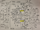
I'm getting to the point where I really just don't know. The fact that the B-E voltage doesn't stay changed tells me something is pulling it back. Best guess is the diode thing wired where the schematic calls for a thermistor. Why its doing that I don't know. Also no idea why the drivers would be getting hot. They don't seem to be flowing excessive current based on the voltage readings. Would be really helpful if there was a schematic showing your unit as it is built rather than relying on one that we know isn't quite an exact match.

weird noises could be something dumb in the preamp if the inputs to the power amp aren't still jumped to ground.
 
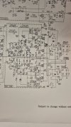
*** ignore this reply, see further down for revised schematic and STV-3's ***

I'm wondering if the STV-3 diodes were never a JVC thing and someone's added them.
Would it make sense to source an equivalent of the TH SDT-20 thermistors and try that?

Even the schematic the amp came with both the user manual and service manual only mention thermistors

Is there a generic example of when components pull back when unhappy that you can describe just so I can visualise it? Might help me carry on
 
Last edited:
*** update, latest post has revised schematic

Oh I just proved the diode change theory wrong. Here's someone else's 5003 and it has the same mount and STV-3's by the looks
 

Attachments

  • Screenshot_20240220_004812_Chrome.jpg
    Screenshot_20240220_004812_Chrome.jpg
    67.2 KB · Views: 7
Last edited:
Hey @gadget73 here it is!

STV-3 shown in image 20240220_005647.jpg

Sorry, I didn't realise there was a revised schematic in the bundle of paperwork

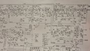
Plus I took some pics of the rest. See this dropbox link for hi res


1708351422691.png
 

Attachments

  • 20240220_005629.jpg
    20240220_005629.jpg
    90.2 KB · Views: 8
  • 20240220_005647.jpg
    20240220_005647.jpg
    112.1 KB · Views: 5
  • 20240220_005700.jpg
    20240220_005700.jpg
    95.4 KB · Views: 5
  • 20240220_005705.jpg
    20240220_005705.jpg
    108.2 KB · Views: 5
  • 20240220_005705_1.jpg
    20240220_005705_1.jpg
    108.2 KB · Views: 8
ok so refresh my memory on the STV thing again, are you using the original parts or is that a string of diodes now?
 
ok so refresh my memory on the STV thing again, are you using the original parts or is that a string of diodes now?
Originally I had the STV-3's in but recently replaced with string of uf1004 I think they are. I did that too rule them out I guess. I have a Pioneer sx-770 I'm working on and actually had a bad STV-3 in it so did the same string and it worked.
I was careful to make sure no leg contact with case on both
Just be I dug up two of the STV-3 in my stash and they test ok I think. Using old school transistor tester with diode function
Is there anything you can see that draws a different story from old schematic to this one?
I need to sleep now will check in morn. .cheers
 
do you have one of the original STV to confirm what the voltage drop is vs the UF4004 ? just want to make sure its similar enough.

so the 680 ohm resistor, R433, R434. That should NOT be present with the diode string. Looks like that should actually have a jumper where the 680 is, or maybe its already wired across because of where the STV leads are. Either way its not part of the circuit. Ohm check from the stripey end of the X407 and it should read zero ohms. With the STV out, you should read open circuit between R453 and the base of X407. On the version with thermistors, R453 does not exist, so not quite sure where it might live on yours if the board wasn't revised to give it a hole. Expect it somewhere in the neighborhood of the bias pot though.

The bias pots are a different value too, 500 ohm on the old schematic vs 200 on the one with the diodes. What value is in yours?
 
do you have one of the original STV to confirm what the voltage drop is vs the UF4004 ? just want to make sure its similar enough.

so the 680 ohm resistor, R433, R434. That should NOT be present with the diode string. Looks like that should actually have a jumper where the 680 is, or maybe its already wired across because of where the STV leads are. Either way its not part of the circuit. Ohm check from the stripey end of the X407 and it should read zero ohms. With the STV out, you should read open circuit between R453 and the base of X407. On the version with thermistors, R453 does not exist, so not quite sure where it might live on yours if the board wasn't revised to give it a hole. Expect it somewhere in the neighborhood of the bias pot though.

The bias pots are a different value too, 500 ohm on the old schematic vs 200 on the one with the diodes. What value is in yours
 
Hey @gadget73
I've removed the 680 ohm resistors that I had added in.
I've removed the uf1004 x3 DIY diode from circuit and tested, image 3 attached. Image 1 contains one of the original STV-3 with its broken leg but was able to make contact. Image 2 is another STV-3 which may be the other one from this unit or from a parts unit I pulled apart some time...
For the ohm check I have for x407 - base to ground was fluctuating between 50k and half a meg ohm, b to c was 4.7k ohm (solid, no change) and b to e was 50k and climbing (heaps of change), it was going up fast
The bias trimmers are 200ohm
The resistor Ill need to search for after work, isn't clearly sticking out to me but will check again
Thanks!
p.s. if I remember to when I'm in the office Wednesday I'll take that revised schematic in and do a hi res scan just so it can be shared with anyone else who has this model revision in future.
Also thanks so much for your insights so far, I really really appreciate it :)
 

Attachments

  • 20240220_102133.jpg
    20240220_102133.jpg
    78.3 KB · Views: 5
  • 20240220_102118.jpg
    20240220_102118.jpg
    84.6 KB · Views: 5
  • 20240220_102045.jpg
    20240220_102045.jpg
    87.5 KB · Views: 5
Last edited:
Do you have a digital meter with a diode check function? Trying to confirm the voltage drop across the junctions. The ohms don't matter here.
 
I do but it won't see a triple diode. Pretty sure it won't go over 1vdc and we'd expect like 1.5 on an STV-3 I think?
 
I'm sure I've seen a solution to this that's described a little less wordy I think it involved a 9v battery and some resistors
 
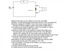
9v, a resistor, and a meter across the diode string will work just fine. Something in the 1k - 2.2k range will work. Mostly just want to confirm the voltage is very similar. It should be, but at this point when things don't seem to make sense its worth confirming.
 
Hey @gadget73

Hope you slept well. Nearly midnight here

I hope I've got this setup correctly
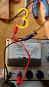
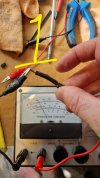
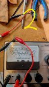
Com meter > into neg battery > pos battery > resistor > anode > cathode to positive meter

I couldn't get a read on diode mode but measured using volts dc. One pic has a spare STV-3. The other is the series of diodes. The 9v battery is brand new bought today and reads 9.76v on meter.
 

Attachments

  • 20240221_233137.jpg
    20240221_233137.jpg
    84.9 KB · Views: 7
  • 20240221_233433.jpg
    20240221_233433.jpg
    110.5 KB · Views: 7
Back
Top Bottom