

You are using an out of date browser. It may not display this or other websites correctly.
You should upgrade or use an alternative browser.
You should upgrade or use an alternative browser.
Cheap Chinese 6P3P kit
- Thread starter Big & Pink
- Start date


Kegger
R.I.P. 1/12/1966 - 6/1/2017
I'll look at those pic's.
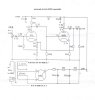
But just so were clear on how the rectifier and ground wiring should go.
The schem might have been a little unclear, I cleaned it up a bit though.
The bottom side of the caps should be ground, an where the center tap
of that power tranny goes, the top side of those caps should be your B+.

But just so were clear on how the rectifier and ground wiring should go.
The schem might have been a little unclear, I cleaned it up a bit though.
The bottom side of the caps should be ground, an where the center tap
of that power tranny goes, the top side of those caps should be your B+.
Attachments

Kegger
R.I.P. 1/12/1966 - 6/1/2017
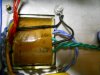
What are those 2 black wires going to chassis ground?
One looks like the center tap of the heaters feeding the preamp tubes,
that looks fine, what is the other one?
And the yellow wire I'm assuming is the high voltage center tap, and if
so should get connected to ground just like your heater canter tap did.
(then you measure yur high voltage B+ DC voltage from ground to rect)
Kegger
R.I.P. 1/12/1966 - 6/1/2017
Not sure what/how your measuring, but with no current/load being drawn
from the supply you should have about half that, or 450v DC at that point.
(if you've got 330v AC from center tap to each high voltage leg that is)
I'm going to be offline for a while, I'll check back later..
from the supply you should have about half that, or 450v DC at that point.
(if you've got 330v AC from center tap to each high voltage leg that is)
I'm going to be offline for a while, I'll check back later..

