• The move to the new server is done. There are some software and database maintenance updates in process. This has us passing the hat around to help out. We appreciate any donations. Seriously, even a dollar helps. The payment page may be found here - https://www.audiokarma.org/support.html

Citation II hack

I hooked up the feedback loop,and the amp sounds pretty good,it still needs some tuning,and the ecc81 mod(awaiting parts).The next thing is the inrush limiting,I have a solid state relay I plan on bypassing with a resistor until the B+ is mostly charged,then turn it on.My thoughts are to charge a cap from the 6v meter supply untill the ssr input reaches the 1-3 volt turn on voltage.
 
An answer to one of your questions is yes, if the plate is open the screen will try an
draw All the current, which could cause a screen resistor and or that tube to go bad.
 
Thank you,I was wondering if that was what killed the resistor,it was a 2 watt 270 ohm,I'm not sure if it was film or wirewound,it dosen't look bad,just a small chip in the glaze ,but it is open
 
I'm still waiting on the balance pots,I tried a pair EL34's in the amp to see how it would sound,but the grid resistor started getting hot with a test signal,I've been able to try it in other amps without a problem,Would I have to connect pin 1 & 8 on the output tube socket to be able to try a EL34? This is the first amp I've ever tried to experiment with,I have repaired many amps,and built a few,but without changing the circuit.
 
The citation II is not the kind of amp to be playing with "different" tubes in it.

B+ is to high for anything but 6550/KT88, it is fixed bias with SS power supply
so no slow ramping of Current an Voltage to catch the tubes for bias as there
"warming" up, and yes when using EL34's pins 8 and 1 should be tied together.
(also the primary impedance is quite low demanding high current to work well)
 
I see what you mean about the impedance,I thought the Cit had 5000 ohms,but it has 3800,The Dynaco mark 2 has 4300,but B+ is a little higher with EL-34's(465v)and the BTH has 6600,with 450v I think,I am using old mullards(I have about 30 of them)so the voltage shouldn't be a problem,But the mismatch would probably throw the frequency response out of whack.I was thinking that the original EL34 circuit was still together waiting for parts,so I would try it.
The resistor changes you mentioned,I would need 1w correct?I was not able to get a quality 20k pot,I was able to get 35k,so if I subtract 7.5 k to the resistors in that circuit,it should be the same,right?
 
Last edited:
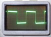
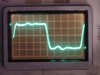
I started working on the feedback circuit with the original feedback circuit,using EL-34's and 6550's using the original circuit posted.I had to use a variable resistor to tune the circuit,and tried different caps.this is a 10k square wave.@ about 10 watts
This is the result,Does anybody know what's happening with this?
there is a cap and resistor I may have to change C3 and R7.
I also have a low frequency stability problem around 7hz if I thump it there is a slow oscillation with no signal.
I used .33uf caps instead of the .25 used in the HK,the BTH used .5 I split the difference.
 

Attachments

  • P1010030.GIF
    P1010030.GIF
    132.1 KB · Views: 62
Last edited:
S -- Three things to do first:

1. For the purposes here, perform all your square wave testing at about a 1 watt level. That way, the amplifier will remain in Class A and prevent any weird Class B issues from affecting the display.

2. Always monitor all your square wave testing on a properly loaded 16 ohm tap.

3. Make sure that your FB level is not exceeding 20 db. This can be checked by driving the amplifier to an output of 5 volts on the loaded 16 ohm tap with the loop disconnected from the OPT tap and grounded. Then, connect the feedback loop and see what the output level has dropped to. If it is less than .5 volts, then it is providing a FB factor of greater than 10, meaning that the FB loop is operating at greater than 20 db.

Once you are testing with proper procedure, and know that the feedback level is not overly excessive, take some more pics of a 10 kHz square wave and we can go from there.

You've got quite an aggressive project here. It should be very neat when it's all finished up!

Dave
 
I have one problem,I cannot hook up anything to the input with the Fb disconnected,I have too much gain,If I replace the input resistor(1m) to ground with 100k will that lower the gain?
 
No, but if your input stage is a pentode tube, you can reduce the input resistor to 100K, and then insert a 1M resistor in series with the source applied to that 100K resistor. This will create an 11X reduction network at the input to help deal with the excessive gain.

Dave
 
It seems I had a feedback problem coming from the load resistor wiring.
Ok feedback loop removed from opt and grounded, .004 v in yeilds 5v out
fb ungrounded = 4v Hooked up .16v I used a varible resistor to get the best square wave as previously posted,so it seems I have way too much feedback.
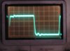
If I adjust the resistor to yeild .5(20db) My square waves are slightly rounded in the left side and fairly flat, at 10k there is a more rounding at the left with a tilt up.Raising the wattage dosen't change anything.What does the resistor and cap across the output of the output transformer do?I am currently using the EL=34's since the driver circuit was originally designed for it,although it's a little rough on the tubes at full power,100 ma at 40 watts it starts clipping.
 

Attachments

  • 20db1khz1.GIF
    20db1khz1.GIF
    82.9 KB · Views: 29
  • 20db1khz2.GIF
    20db1khz2.GIF
    135.9 KB · Views: 25
  • 20db10khz1.GIF
    20db10khz1.GIF
    126.5 KB · Views: 25
Last edited:
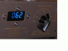
In case anyone is interested in the digital bias meter scheme,the AC balance is still easy to adjust.You set the DC balance with no signal,then apply the test signal,and adjust the AC balance according to the milliamp draw on each tube in the pair.You just can't use the AC balance positions with this meter,as it dosen't do negative voltage
 

Attachments

  • meter.GIF
    meter.GIF
    79.8 KB · Views: 48
Last edited:
S -- So we have progress! I know you posted various copies of schematics your design is taken from, but a fresh, accurate copy would help here.

I suspected as much that the feedback level was extremely high, and apparently you found that is the case. For lack of any other data at this point to work with, I would continue to go forward targeting a 20 db level. This is a good level -- that when properly applied -- will adequately lower distortion and internal impedance, allow for solid stability, and all while not causing the amplifier to sound choked.

The rounding you are seeing now is due to excessive loop and HF gain compensation in the circuit, and will require adjustment to achieve a more appropriate response. Understand that at this point however, some values and configurations used will best determined by trial and error.

The Zobel network across the output is used in a number of designs to maintain a load on the amplifier at high frequencies. It is at these frequencies where phase shift in the amplifier -- when completely unloaded -- can reach the point where the negative feedback actually becomes positive feedback, causing the amplifier to "take off". Early feedback amplifiers suffered greatly from this problem, and the Zobel network strapped across the output was one method to help avoid it. For example, take a look at the schematic of the Heath W-3M, versus the reissued W-3AM. In part, a Zobel network was added to help cure the problems of the earlier model.

There is a general process I can help step you through, but first please post an accurate schematic of where the amp is at this point before continuing. Also, may I assume that the LF instability you noted has also disappeared with a more appropriate FB level in place?

Dave

 
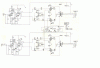
Yes the LF oscillation seems to be gone,and that part of the problem seems fixed. I disconnected the diodes before the last round of testing (before I posted the first scope pics)because I wasn't sure if they would interfere with figuring out the feedback. Here is the amp as it stands without PS.

The FB cap is 127pf and the resistor is 25K If you need a larger schematic I need to edit a larger version and repost
 

Attachments

  • citation26ca7sm.GIF
    citation26ca7sm.GIF
    87.2 KB · Views: 108
OK. That works. Please realize that the adjustments to the FB and step networks require that the actual OPTs that you will be using be connected into the circuit, because these networks are tailoring the response of the circuit and HF characteristics of the OPTs so that an extended HF response is achieved, but is also rolled off appropriately before the circuit gets into trouble. If you use any different transformer, you will simply be adjusting everything to work appropriately for that transformer, and then have to do it all over again for the actual transformers you will be using.

Dave
 
I will be using the Citation transformers,The current mesurements are with them installed,The Kt120 schematic reassigned the outputs to the next lower ohms tap(16=8) to put more load on the KT-120's as well as the DC restorer diodes(Bob Carvers design)
 
For this exercise, let's use the transformers as they were designed (i.e. 16 ohms = 16 ohms). NORMALLY, such exercises as Carver is doing here does increase power, but decreases power bandwidth significantly. However, with the use of KT-120s as part of the modification, I do not know that for sure -- but I do surly wonder.

So start with a 16 ohm load on the 16 ohm tap, and your scope connected there as well. Now remove the step network across the input stage plate resistor and the phase shift cap across the FB resistor. Install a proper feedback resistor that establishes 20 db of NFB from the same tap the Citation originally used for global NFB. Turn the unit on with a 10 kHz square wave applied and see if it will remain stable in that condition. General ringing is fine, but if it oscillates (probable), place a 100 pf cap across the FB resistor and see if that will stabilize the amp. If necessary increase the size of the cap to achieve basic stability.

When this has been achieved, use your sine generator and output indicator to determine which cap value creates a flat frequency response to at least 100K. When you do this, make quite certain of any deviance in the output of or sensitivity of your generator and indicator with regards to frequency. Once these are noted, adjust the cap for a true flat response to at least 100K and report back!

Dave
 
Correct. With the step network removed and a well undersized FB cap in place, a 10kHz sq wave should show a very strong spike extending well above the wave top, likely followed by several other spikes as well. All of the rounding nonsense you saw earlier will be gone.

Once you have determined the optimum FB cap with your response tests, then we can move on to the step network.

Dave
 
Well.. I had an eventful evening,I finally found what I did to cause the feedback problem the other day,it happened again,I hooked the o-scope ground to the opt hot instead of ground,the output was shorted through the o-scope and signal generator grounds.
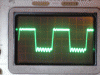
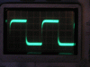
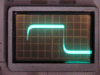
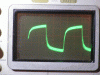
I disconnected the step attenuator for all tests,each pic is titled for the test taken.I am amazed at how well it performs without the step attenuator I am not sure if any improvement can be made.Although there are some slight bumps in the square waves.the pics are a little blurry because my camera has trouble in low light.The fb cap is 27 pf and the resistor is 38k
 

Attachments

  • 1Ksno feedback no step.jpg
    1Ksno feedback no step.jpg
    146.6 KB · Views: 49
  • 10ksfeedback no step.jpg
    10ksfeedback no step.jpg
    147.4 KB · Views: 46
  • 20ks feedback no step.jpg
    20ks feedback no step.jpg
    147.2 KB · Views: 41
  • 20hz feedback no step.jpg
    20hz feedback no step.jpg
    145.8 KB · Views: 35
  • 10k feedback no step.jpg
    10k feedback no step.jpg
    145.4 KB · Views: 34
Last edited:
Back
Top Bottom