• The move to the new server is done. There are some software and database maintenance updates in process. This has us passing the hat around to help out. We appreciate any donations. Seriously, even a dollar helps. The payment page may be found here - https://www.audiokarma.org/support.html

Citation II hack

The EF86 is a fine tube, (many people like them where this one is being used)
(even if it was to be "triode strapped" it still has it's followers)

And the 12AX7 has it's places, but not a good choice for a tube that's actually
sitting in front of the output tubes an driving them, combine that with the EF86
gain then a lot of gain from the 12AX7 and it's just not a very good setup there.
(to much overall gain, an the 12AX7 makes a bad "driver" tube for the outputs)
 
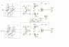
Ok,so this is the current recommended Schematic?,What wattage should the resistors for the 12BH7 be ? There should be a fair ammount of current,Right?
I realize I'll have to recheck the fb res/cap again.
I would like something around .5 to 1v input for full power I think. I seem to get the most out of my current preamps around that.
 

Attachments

  • citationkt88sm.GIF
    citationkt88sm.GIF
    74.4 KB · Views: 59
I'd run 2 watt units at the plates and cathode for plenty of over rating. Also, the dropping network to derive the 350 volt supply point will need adjustment with the new inverter circuit drawing much more current. If the overall B+ will allow it, I'd even consider upping that point to 375 volts or even 400 possibly, and target the plate voltage of the EF86 at about 95 volts or so.

With your target sensitivity requirements, the EF86 will need to operate in pentode mode if 20 db of NFB is used. Should make for a great design!

Dave
 
B+ is around 460,so I won't have any problem getting 400,Does input impedance make any difference between preamp and amp,also should I use an input cap to block DC?
 
I think Dave's pretty much got yu covered. :thmbsp:

Also if yu still wanted to loose a little gain R4 the plate load for the EF86 you could
go down to say 75k, and I personally don't use input caps, it's your choice on there.

Also the 1meg input/grid to ground I'd use something more normal at like oh 270k or
less, and then use a grid stopper on the EF86 of 10k or so there to.
 
Where would a grid stopper on the EF86 go,I've heard the term grid stopper,but I am not sure what it's for,or how it's used.
 
It goes right on the socket/pin of the grid of the tube.
Helps in preventing any oscillation and or picking up any super high frequency crap. :)
 
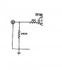
The stopper resistor goes between the input grid and the input jack, with the grid return resistor on the jack side of the stopper resistor.

The stopper helps the input stage deal with any overload signals, and also helps to provide a measure of RFI protection as well. For triode input stages, the resistor also helps to isolate the input capacitance of triode input stages from the output of the preamp. Some preamps deal with capacitance across their output better than others, so the resistor helps to isolate the input capacitance in those cases.

Dave
 
So,it goes between the input grid of the tube and the input,after the 270k shunt to ground?
what should the value be?
 
So it goes..

Input, grid to ground resistor, grid resistor.

Would look something like this added pic here..
attachment.php
 

Attachments

  • input.JPG
    input.JPG
    11.5 KB · Views: 106
OK, will do,I'll let you know when the parts get here,and are installed.It's going to take a while. I have to pull the boards to make the changes,hindsight, I should have gone with larger fork type turret boards Thanks again guys
Scott
 
Well... I reconfigued the amp as per the last schematic input shunt is 270k R3 is 85k 10k grid stopper added also
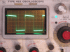
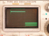
Without fb .023v =5v with fb .18v =5v, so the overall gain is about right.
There seems to be a problem with the fb loop(possibly R6?)as I have to use 3k as a fb resistor and 470pf,and there are ocillation problems within the square wave when I raise the output from .5v to 5v
The second pic is @5v It looks not too bad @ .5v The best fb as far as looks is 5v without to 1.5v with feedback (I don't know the DB value)Then I can turn it up without problems.
 

Attachments

  • 1knofb.GIF
    1knofb.GIF
    115.9 KB · Views: 32
  • 1k1watt20fb.GIF
    1k1watt20fb.GIF
    76.6 KB · Views: 30
Last edited:
I don't have anything to add for the feedback tweaking, hopefully Dave will though.
 
I Know,back to the problem I had before.I'm still trying to find out how the Leak did it,possibly the EF-86 is configured differently,for less gain.I have to study it a little longer.
 
In the TL50 pin 1 of the EF86 is tied to B+ with a 1.5m source,on the (BTH)Cit II it's tied to B+ with a 390k
 
Last edited:
Back
Top Bottom