


I am still unsure why I agreed to tackle this ancient monster amp. It is 40 years old and was eating output transistors like there is no tomorrow. Left channel only. But with 12 MT-200 transistors per channel it is quite annoying. And expensive. By now the board is ruined by the many repairs done to it. As the designers set the various currents rather generous many resistors overheated and blackened the boards. I decided to not total loss it but rebuild it. Unfortunately there are many iterations of the design but I just stuck with the one I had in hands. Which is one of the later versions.
I used KiCAD to redraw the sister board. This has the fewest components and would prove feasibility. The trick is to not create a schematic but to remove everything from the board and scan both sides. With GIMP I cleaned the scans up somewhat. Making sure the dimensions of the scans were exact I added the scans (bottom one flipped) as image in two unused layers (User.1 and 2). I then created pads in a total of six sizes for the wires of the components. I used the Edge.Cuts layer for the drill holes for the many screws. Then I drew the traces and the silk screen. Took me more than a day to complete making this repair already completely uneconomical. But it does nicely show the validity of this method.
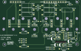
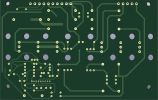
I used KiCAD to redraw the sister board. This has the fewest components and would prove feasibility. The trick is to not create a schematic but to remove everything from the board and scan both sides. With GIMP I cleaned the scans up somewhat. Making sure the dimensions of the scans were exact I added the scans (bottom one flipped) as image in two unused layers (User.1 and 2). I then created pads in a total of six sizes for the wires of the components. I used the Edge.Cuts layer for the drill holes for the many screws. Then I drew the traces and the silk screen. Took me more than a day to complete making this repair already completely uneconomical. But it does nicely show the validity of this method.