• The move to the new server is done. There are some software and database maintenance updates in process. This has us passing the hat around to help out. We appreciate any donations. Seriously, even a dollar helps. The payment page may be found here - https://www.audiokarma.org/support.html

Component replacement challange, informed upgrades to an Sx, paging Leestereo

cwh

33
Currently a parts changing enthusiast who is slowly going down the road to audio electronics proficiency. Or at least "I fix more than I destroy."

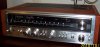
I just pulled down from the shelf an SX-780 project that's been waiting for a rebuild. Forgot how clean it is, pleasant surprise. Worthy of attention despite the powerpacks and it's mid-fi standing. Back when I originally found this discarded receiver I pulled the shorted darlington and go it out of protect. I ordered the standard 780 rebuild fare as seen in the annals of AK.

So I'm chugging along today and the more I got into the unit the more I felt obligated to put parts in that may improve on Pioneer's engineering. Leestereo's colorful, clear and concise restoration posts have inspired me to think that there are certain areas in audio circuits that can be easily improved and an informed professional would definitely do the upgrades. My takeaway from his rebuilds is typically power supply caps are upped. Certain resistors are replaced and of course signal path electrolytics are swapped with film. RIAA tweaks and other stuff that are very specific numbers wise.

So my soldering has paused as I've come up on some 100uf 25v bypass caps which I see are in a circuit with a working voltage of 23. Naively I'm thinking those should be upped to 35v and increasing the capacitance to 200uf will be good too.

So any suggestions AKers on key areas that you always improve upon in a Pioneer, or in vintage amp circuits in general?

-Carl
 
Register to hide this ad
Agreed. 100uf 35v is fine. Concentrate on the voltage ratings vs rail voltages. If the rail voltage is 5v or less to the cap rating, change the cap to the next voltage. Today's votlages are higher than they were 40 years ago, so you have to compensate for that too. I've gotten to the point where I just automatically bump up the voltage on ALL caps 1 rating, and sometimes 2 if the next isn't available.

Any caps that are SMALLER than 4.7uf, I replace it with a film cap. Size can be a stopping point. But as long as there is space, use a film cap.

Certain units benefit from "AUDIO" grade caps and some don't. I did a comparison of UKL/UPW on one channel and UPW/UKW and UFW caps in the other channel on my 790 (Black Dial Face of the 780). 100_1852.JPG
There was no discernable difference between the two channels. I had 3 other friends listen to it and did not tell them what they were listening for. Not one of them could tell a difference between the channels. I then replaced all the UKW and UFW with UKL's and put the UFW/UKW's in my parts bin. AFAIC the 780 doesn't show any improvement with the "AUDIO" grade over the UPW/UKL's, and the Standard Low Noise(UKL) and Low Leakage/Low Impedance (UPW) show an improvement over the factory stock Nichicon/Sanyo/United Chemicon's of the 70's. As far as I can tell the 780 has basic circuitry, nothing fancy that requires anything more than standard caps. It will show reliability improvements in all circuits by replacing the small sky blue Sanyo's and the flat green mylars right up against the Tone pots. Replace them all with ECQ's (if not available then the new Nichicon yellow films) or other films. These are for more reliability, as the Sanyo's break down hard and cause a lot of problems.

Power supply area. Check and resolder the power supply diodes and regulators. These will get hot enough to desolder themselves causing breakdowns. Use longer leads on the diodes and regulators. Also add heatsinks or larger heatsinks to them. On the regulators use mica insulators and nylon screw and nut as the back of the casing is live having circuit voltage on it. You DON'T WANT TO GET ZAPPED by these regulators.

The 8200uf/63v Main Filter caps can be replaced with 10Kuf by 100v Nichicon's. These will fit inside of the original can's with no problem.
Bump all of the Power supply caps UP by 1 voltage rating at least. These are the most affected by the modern voltages. Also replace the zener diodes on the power supply. These are run hard and can be right on the edge of dying.
 
I agree with mtf, it depends on where and what, going up one value in capacity is a lot safer than doubling it. In some cases is important to stick to the exact value and type.
 
Old: Had problems with them in my 737, 939, 790 and a couple Sansui 2000's. I replace them pre-emtively in the tone boards now.
 
Hey guys thanks for the replies but the nature of the my post was completely lost in translation. I'm very familiar with most the content on AK, both read and applied.

I was asking if professional or seasoned audio repair people have certain components (certain stages) that they always upgrade when rebuilding.

I mentioned Leestereo's rebuilds as an example and paralleled a similar stage on my rebuild where I took pause. http://audiokarma.org/forums/index....d-upgrade-of-a-marantz-2235b-receiver.610748/
Non-signal Path Capacitors
The local DC filtering capacitor for the preamplifier stage (CE25), was originally 220µF/35V and the replacement was a 470µF/35V low ESR type. Similarly, the original decoupling capacitors for the first gain stage (CE03, CE04) were 10µF/35V and these were replaced with 22µF/50V low ESR types.
 
I think Larry had addressed your curiosity.
Not much can be had by improved circuits/components(?), whether the audio grade are used or different values are substituted.
Most if anything is transistor subs with better modern equivalents. Resistor wattage, which support the circuit without compromising the reliability. And as you mentioned about the films.
Oh, and the occasional back EMF diode across the relay coil.
All done to improve reliability.
The SX-780 is a damn nice set as is.
 
Old: Had problems with them in my 737, 939, 790 and a couple Sansui 2000's. I replace them pre-emtively in the tone boards now.

Thanks Larry, very interesting.

Hey guys thanks for the replies but the nature of the my post was completely lost in translation.

Sorry cwh that l didn't understand your question fully, l am in no way experienced enough in circuit design to deviate from Pioneers original values in capacitance without knowing outcome. I usually keep capacitance values the same and go up one or two voltage ratings.

All the best with your build!
 
Regarding increasing capacitance values, there is typically no problem increasing the capacitance rating of the local decoupling/power supply capacitor; especially for small values less than 1000µF. IMO, a 2X-3X increase is acceptable for most small capacity capacitors whose purpose is solely DC filtering. In these cases, the extra load on the power supply transformer and diodes is minimal. However, the extra load would be a consideration when large main power supply capacitors are to be replaced; in that case, a more conservative approach is warranted, e.g., if the stock main filter capacitors are rated at 15,000µF an increase to 18,000µF (a 20% increase) would be acceptable, but beyond this value may be inviting problems.

The original capacitance rating and types (e.g., electrolytic vs. film) specified during manufacturing were often limited by capacitor technology of the day, the cost of part and the physical size (finite space available on the PCB). I am certain that the original designers would have opted to use today's better parts had they been available or had not been constrained by profit considerations. Indeed, there is general trend of using larger decoupling/power capacitors as one goes from the early solid state designs to the later "Golden Age" solid state designs of the late 70s.
 
So pretend I found a otherwise mint receiver with it's boards stripped of their components and I also had a bag of NOS resistors, capacitors etc. My focus here is, are there better materials available to me than what was originally installed? Not interested in wholesale replacement or re-engineering. No desire to make everything bigger or defy physics with magic while increasing Mouser's bank account. If I wanted to throw out all the old then my piles of vintage audio stuff wouldn't exist. However my experience pales to someone who's had scores of amplifier circuits under their soldering iron. Seasoned professionals and enthusiasts have empirical knowledge of what works and what doesn't when rebuilding. The influencing factors, I'm sure, can be numerous and quite specific but generalities can be distilled.

I would assume that there probably is some room to improve an amplifier's circuit through changes in components. I could see the limits placed on design by cost and available technology/size. Those smart engineers probably balanced that with what they could deliver giving the best bang for the buck. AK posts pay a lot of attention (good and bad) to capacitors. Certainly there's little argument that today's technology can provide smaller, cheaper and more robust caps compared to the past. Without the manufacturer's constraints, small signal path electrolytics can be improved with film and potentially less robust lower voltage (<16v) ones can be replaced with their smaller sized higher voltage counterparts. Now I understand that material type and value of capacitors play an important role in circuit design but there must be areas where choices where made to satisfy a bare minimum. Certain power supply capacitors for instance. I noted Leestereo's post as what I assume is an informed design improvement by increasing the value of the shunt and filter capacitors. Informed meaning; the decision produced an end product that was favorable to his client.

As with capacitors I'd think certain resistors could use an updating. Beyond the highly subjective noise characteristics, there should be modern resistors that have the ability to handle certain stages with more robustness than what was available at the time of manufacture.

Semiconductors are the exception. These I think, unless damaged or noisy, best left be. Speaking of shared knowledge specially q19,20,25 and the SX-780. If not for all the posting regarding them I would've left them alone. If I observed solder joints needing a touch up then they would've been hit. Instead I beefed up the heat sinks and subbed new transistors.

I'll wrap this up with an analogy. Certain aspects of vintage gear can be compared to an old car riding on original bias ply tires. By changing them with their cheapest modern equivalents provide major improvement the safety and comfort of the vehicle. An expensive tire in the same size wouldn't provide such a return. Nor would wide low profile rubber on carbon fiber wheels and the car potentially could be compromised.

Just for the score keepers, for me it's Nichicon Pws and KLs with Kemet or Wima films where I can fit them.
 
Last edited:
Regarding increasing capacitance values, there is typically no problem increasing the capacitance rating of the local decoupling/power supply capacitor; especially for small values less than 1000µF. IMO, a 2X-3X increase is acceptable for most small capacity capacitors whose purpose is solely DC filtering. In these cases, the extra load on the power supply transformer and diodes is minimal. However, the extra load would be a consideration when large main power supply capacitors are to be replaced; in that case, a more conservative approach is warranted, e.g., if the stock main filter capacitors are rated at 15,000µF an increase to 18,000µF (a 20% increase) would be acceptable, but beyond this value may be inviting problems.

The original capacitance rating and types (e.g., electrolytic vs. film) specified during manufacturing were often limited by capacitor technology of the day, the cost of part and the physical size (finite space available on the PCB). I am certain that the original designers would have opted to use today's better parts had they been available or had not been constrained by profit considerations. Indeed, there is general trend of using larger decoupling/power capacitors as one goes from the early solid state designs to the later "Golden Age" solid state designs of the late 70s.
Hey thanks Leestereo for answering the page! My last post had been typed throughout the day and newer comments weren't seen until it went up.

Could you share why you increase uf value of those power supply caps?

I'm hoping (early Boxing Day gift?) that you might offer a cheat sheet for a freshman fixer. A sort of generalized paint by numbers approach towards updating circuits. Your rebuild threads have forwarded my of learning much more quickly than text books. I'd actually like to find a Marantz to follow along with. I will say I'm ok with being a ways off from the theory of F values and subbing smaller value films for filtering. Also RIAA circuit manipulation.

Carl
 
That cheat sheet HAS to be model specific for capacitance INCREASES. Replacing with like values is no problem.
remember, old e-caps used to be -20% +80% tolerance - todays can (check the data sheets) be a lot tighter spec.

interesting news about the green mylars.on the tone boards.
 
Look for rcs16 post for stk replacement. I have built a set and it made a difference. I have been playing them for a few weeks now. With no problems. Gain a little more bass and a more clearer sound.
 
For the skyblue solid aluminium Sanyo's I was recommended (by you guys) replace them all and indeed there was not a single one NOT leaky, most 1 uF were more leaky than a 100 uF normal alu cap..
There exist white Elnas, too, probably same problem to expect there.

But I am not aware of any problems with the green films. How do they fail?
Checking df on the lcr meter they seem comparable to others...
 
Last edited:
A reply from a different Lee...

I've always found better results by squeezing in WIMA films in the signal path rather than upping the value (uF) of every other capacitor in the circuit. Where a WIMA is physically too big, use a Nichicon KL with a 1uF WIMA film across it. Some people go crazy with Panasonic this and that everywhere until the inside looks like a rainbow. Me, I just stick with Nichicon KLs/KWs, but I might try PWs next time.

Lee.
 
Last edited:
Look for rcs16 post for stk replacement. I have built a set and it made a difference. I have been playing them for a few weeks now. With no problems. Gain a little more bass and a more clearer sound.
Great news, congratulations. The new ops blows away the old stk, it is the same onsemi family of bjts that folks are using in a 1980 upgrade. the 780 design is very close to the 1980 design, topology wise.
I did simulate the 780 design, wonder how close the numbers are in comparison of sim vs actual design. anyone have a test setup for that?

Hey Carl, ckt design and component selection are all part of the equation. I look at the totl designs from many mfgs and compare them to say a 780, you can see where they did a better design and components since they had more $ to play with. As leestereo says we are fortunate today with improved comps so that alone with out a design change usually improves a design. We can see so many design examples with free access to service manuals.
The green films are iirc mylars, know one would choose a mylar in a new design.
Of course if you can use a film over a ecap, you are better off in general. you know how it goes as far a quality, mylar,polyester rolled,polyester stacked,... polyprop, teflon, polystyrene.
 
Last edited:
Old: Had problems with them in my 737, 939, 790 and a couple Sansui 2000's. I replace them pre-emtively in the tone boards now.
Larry I too am curious about the green mylars.
What problems did they present?

Side note, I've mentioned in past I live not far from the old Oak Knoll. Thought it'd be of interest that the property is finally being developed. One sticking point was a remaining building of historic value. Just read that it will be saved or they'll attempt to....

Carl
 
Back
Top Bottom