

You are using an out of date browser. It may not display this or other websites correctly.
You should upgrade or use an alternative browser.
You should upgrade or use an alternative browser.
CR1020 voltage issue
- Thread starter Monnich
- Start date
Looks like TR714 and/or TR715 is not working as they should.
Can you measure the DC voltages around each one and post results. E-? C-? B-? format.
Attachments

Awesome i will check that when i get home from work and give you an update thank you so much for the helpLooks like a broken copper trace or bad solder connection between the -NB terminal and the emitter of TR715/R716/R718 solder connection.
Should see -33vdc at the emitter of TR715.
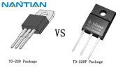
Will do as soon as the railroad releases me from their grasp lol.Look over the board for any possibly iffie solder connections. Especially the TO-220 transistors.
View attachment 3834330
Ok i re flowed most of the solder on the board and the voltage at the emitter went up from 7 v to 11 v unfortunately tr704 had issues lf some sort snd burnt itself upLook over the board for any possibly iffie solder connections. Especially the TO-220 transistors.
View attachment 3834330
Try measuring resistance from -NB pin to TR715e, should be less than 1ohm.Should see -33vdc at the emitter of TR715.
Again check solder on that -NB post

Love these old pieces and watching the local pro's guide ya. Good stuff.

Measured it and and got 0.5 ohmsTry measuring resistance from -NB pin to TR715e, should be less than 1ohm.
Again check solder on that -NB post

Thanks so much for all the help guys turns out whoever was in here before me decided to install one of the transistors backwards i replaced it and and everything is right now .
 Well, good job. TR715?
Tr714 actually. Now it ive got relay click and it even plays music on the one channel i have in although it dosent get very loud?
Check the collector voltages of the 4 output transistors. Should be around +/- 49vdc. +B and -B can be measured carefully** on the output transistor's metal cases.it dosent get very loud?
**----- Don't short the metal cases to the heatsink --- You will regret it.

Does it sound the same on both channels?
On the rear panel there is a pre-main coupler switch. Exercise the switch a dozen times. See if it changes anything.
That switch is notorious for getting real dirty. The backside of gear usually has a lot more dust build-up than the front side.
On the rear panel there is a pre-main coupler switch. Exercise the switch a dozen times. See if it changes anything.
That switch is notorious for getting real dirty. The backside of gear usually has a lot more dust build-up than the front side.
Last edited:

Direct mains , also this is my first time working on one of these thank you so much for the help and guidanceAre you still on the dim bulb or direct mains?