• The move to the new server is done. There are some software and database maintenance updates in process. This has us passing the hat around to help out. We appreciate any donations. Seriously, even a dollar helps. The payment page may be found here - https://www.audiokarma.org/support.html

Crossover question

What @Guido57 said, the measurements will show the crossover point, and the output level of each driver. Based on that, you'll modify the woofer or tweeter section, so both drivers cross smoothly without overlapping or cancelling, and you'll tame the tweeter output to match the woofer output level (usually the tweeter sounds louder and need to be attenuated, but sometimes that's not needed)

I'd say: download ARTA (no affiliation), try to make any Freq Response measurement, familiarize with the software screens, do more measurements until you understand what you are doing, and then yo can start setting up your speaker to get more accurate measurements showing what you need.

I usually take small signal measurements right at the center of each driver, 1" of the driver, to see the crossover slope, and overlap the measurements to see if I need to correct the crossover freq. Then, once both drivers cross at the right point, I start doing measurements at 1 meter from the speaker, to see the full response, checking if I need to tame the tweeter to get a flat response, and checking if I need to phase reverse one of the drivers.

"tweaking" a crossover usually implies adding or removing resistors, modifying capacitor values, modifying the inductor values (usually reducing inductance is easier than adding), adding L-pad networks, zobel, and so.
 
Last edited:
The measurements will dictate the next steps. Mounting the crossover externally to allow for easier changes in components while "tweaking" is an option.
I will try to get measurements today. As far as the modifying the crossover components, I wont be able to "tweak" the crossover due to where the crossover is placed.
What @Guido57 said, the measurements will show the crossover point, and the output level of each driver. Based on that, you'll modify the woofer or tweeter section, so both drivers cross smoothly without overlapping or cancelling, and you'll tame the tweeter output to match the woofer output level (usually the tweeter sounds louder and need to be attenuated, but sometimes that's not needed)

I'd say: download ARTA (no affiliation), try to make any Freq Response measurement, familiarize with the software screens, do more measurements until you understand what you are doing, and then yo can start setting up your speaker to get more accurate measurements showing what you need.

I usually take small signal measurements right at the center of each driver, 1" of the driver, to see the crossover slope, and overlap the measurements to see if I need to correct the crossover freq. Then, once both drivers cross at the right point, I start doing measurements at 1 meter from the speaker, to see the full response, checking if I need to tame the tweeter to get a flat response, and checking if I need to phase reverse one of the drivers.

"tweaking" a crossover usually implies adding or removing resistors, modifying capacitor values, modifying the inductor values (usually reducing inductance is easier than adding), adding L-pad networks, zobel, and so.
I got a program already and a calibrating mic. At what level should I set the noise at? I can probably do a sine sweep better. Thanks
 
I set the level before the max saturates the mic input (before it gets yellow). The higher the signal level, the lower the noise level.

You'll see the graphs using white noise and sweeps are very close, if not identical.

Make sure you don't have any "auto level" or any other similar auto-gain setting at the mic input in your sound card software. It's very common to have auto gain settings by default. Disable any gain or auto-gain.
 
I set the level before the max saturates the mic input (before it gets yellow). The higher the signal level, the lower the noise level.

You'll see the graphs using white noise and sweeps are very close, if not identical.

Make sure you don't have any "auto level" or any other similar auto-gain setting at the mic input in your sound card software. It's very common to have auto gain settings by default. Disable any gain or auto-gain.
What about pink noise?
 
I think I use white noise or sweeps. Try it by yourself, compare the graphs. They should be similar.
 
"CTRL A" saves the reading. (or "ALT A", I don't have the software here)
 
Last edited:
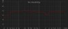
Pretty good! What's that -20dB notch at 2.5K ? It could be the driver phase reversed

Can you measure at the center of the woofer, 1" from the front of the speaker, and then from the tweeter? That way you'll see the crossover freqs. and you can check they are overlapping the way you want.

I'd zoom on the Y axis, you have now 20dB steps, that way the response looks flatter than it is.
 
Pretty good! What's that -20dB notch at 2.5K ? It could be the driver phase reversed

Can you measure at the center of the woofer, 1" from the front of the speaker, and then from the tweeter? That way you'll see the crossover freqs. and you can check they are overlapping the way you want.

I'd zoom on the Y axis, you have now 20dB steps, that way the response looks flatter than it is.
Yes I dont know why there is a notch at 2.5k but I do have the tweeters reversed. When I build the crossover, I had build it at 1.8k crossover point.
 
with the measurements you'll start to see that the crossover point is not like what a calculator "says". That -20dB notch indicates something, perhaps a dead point at your measurement point, but in any case, to me, that indicates the drivers crossing at 2.5K, not 1.8K as you calculated. This is what you want to see to "tweak" a crossover. Real crossover slopes, to modify the components to shape the freq response.

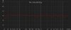
Please check the small signal, measure close to woofer and tweeter, and you'll see the real slope of your crossover. And zoom the Y axis in your graph to 10 or 5dB steps. (5dB is quite challenging, I use 10dB steps)
 
Last edited:
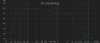
Now the crossover effect is very visible. If you could overlap the 2 graphs, I eyeball the drivers are crossing at around 3.5K.

I'd try another measurement of the woofer with the zobel network, and then proceed from there, choosing the smoother slope. Perhaps you will need to add a capacitor in parallel to add capacitance to the tweeter crossover and make it go a bit lower.

Also, a new measurement from the mid point between the woofer center and tweeter center, at 1 meter from the baffle. That will confirm phase cancelling. If you see a deep notch, you need to invert the tweeter phase and measure again.

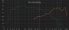
Here I made a FAKE overlap, averaging the SPL, moving the tweeter up, to match the woofer output level, this is the result:

rta1-2.jpg
 
Last edited:
Please check again with the new 5dB scale, and make sure you find the center between woofer and tweeter centers.

I suspect the drivers are cancelling at the crossover freq, but it's hard to see in the 20dB scale. It will be clear in a 5dB scale.

I'd add the zobel to the woofer, and make a new woofer measurement, I hope it will tame that peak at the 2K.
 
Should I invert the tweeters in phase now?
With perfect crossover the two drivers will be in phase at the crossover point and the frequency response will be flat. Inverting the phase of the tweeter will put a deep null in the frequency response. Try it to see if you get a deep null when you invert the tweeter.
With an imperfect crossover the two drivers will not be perfectly in phase at the crossover point and inverting the tweeter will make a difference but not give you a deep null. In that case, choose the phase which gives the flattest response or sounds the best.
 
DYI Audio and Video:
Capacitors

C1 = 5.53 uF
C2 = 5.53 uF
Inductors
L1 = 1.41 mH
L2 = 1.41 mH
Parts Express basically the same. Other online calculators may differ.
 
Last edited:
Back
Top Bottom