• The move to the new server is done. There are some software and database maintenance updates in process. This has us passing the hat around to help out. We appreciate any donations. Seriously, even a dollar helps. The payment page may be found here - https://www.audiokarma.org/support.html

Dead Technics SU-V6X?

colegget

New Member
Hi all,

Hoping to get some information to get a Technics SU-V6X up and running again. I found it in a box after several years and used it for a few days without an issue (the left channel was iffy on the main speaker input but the remote input worked fine so I just used that). When I went to turn it on today, nothing happened - not even the lights on the front. I suspect that there was a power issue at some point earlier in the day as my kitchen appliances didn't work until I reset the outlet. Unfortunately, plugging the SU-V6X into a different outlet didn't bring it to life. I see a fuse next to the power switch but I tested it for continuity and it seems to be fine. I didn't see any other fuses in the service manual but my knowledge of electronics is lacking. Any ideas? I don't know how able I am to fix a larger issue but it would be a shame that it worked fine after several years only to be fried a few days in.

Thanks!
Connor
 
Register to hide this ad
Well, let me take a stab at it. I had an MCS 3842 (Technics) that one day just stopped working. And when I went to turn it on there was nothing. Turned out to be a thermal fuse in the transformer. @SVI2004A helped me to bypass that thermal fuse and now it lives again. Maybe send him a message. He walked me through the entire process, although it was pretty easy. Just had to unmount the transformer, flip it over and then move one wire from one terminal to another.
 
Yeah, I just went back and looked at my conversation with SVI2004A where he helped me to bypass that thermal fuse. All it involved was unscrewing the transformer from the chassis, flipping it over to access the wires, and then moving the brown wire to a different terminal. I can't say for sure that is the issue with your unit but it could be. But good idea to contact our resident Technics expert and see what he thinks. All he had me do was measure some resistance between terminals on the transformer and then move the brown wire. My unit had the exact same symptoms.

Not trying to confuse you here because the transformer in my MCS 3842 is probably not the same as the one in your SU-V6X. But the photo shows what I did. Moved the brown wire to the terminal circled in green and that bypassed the thermal fuse and brought it back to life. SVI2004A just had me measure resistance between the green and red terminals and resistance between the green and blue terminals (unit powered off). Once I gave him those readings he told me to move the brown wire to the green terminal and that fixed the issue. But of course it will be best to deal with him directly. I don't want to offer advice on something that I don't know about as I have never opened up an SU-V6X before and so I have no idea what the wire layout will be on the primary side of the transformer in your unit...
Screenshot at 2026-07-10 21-28-14.png
 
Last edited:
Yeah, I just went back and looked at my conversation with SVI2004A where he helped me to bypass that thermal fuse. All it involved was unscrewing the transformer from the chassis, flipping it over to access the wires, and then moving the brown wire to a different terminal. I can't say for sure that is the issue with your unit but it could be. But good idea to contact our resident Technics expert and see what he thinks. All he had me do was measure some resistance between terminals on the transformer and then move the brown wire. My unit had the exact same symptoms.

Not trying to confuse you here because the transformer in my MCS 3842 is probably not the same as the one in your SU-V6X. But the photo shows what I did. Moved the brown wire to the terminal circled in green and that bypassed the thermal fuse and brought it back to life. SVI2004A just had me measure resistance between the green and red terminals and resistance between the green and blue terminals (unit powered off). Once I gave him those readings he told me to move the brown wire to the green terminal and that fixed the issue. But of course it will be best to deal with him directly. I don't want to offer advice on something that I don't know about as I have never opened up an SU-V6X before and so I have no idea what the wire layout will be on the primary side of the transformer in your unit...
View attachment 3799029
I just sent him a message; hopefully he'll be able to fill me in. Thanks for the suggestion!
 
I just sent him a message; hopefully he'll be able to fill me in. Thanks for the suggestion!
Yeah he really helped me out. Told me what to do and then I sent him some photos. After that a quick resistance measurement and moved one wire. Hope it works out for you. The SU-V6X is a nice amp. And I think he is in Australia as well so just be aware of the time difference.
 
Most likely that thermal fuse…

The primary side if the xfmr will vary on suffix (region code)
Whilst many have 3 terminals, multi tap ones have 7
 
So if you remove the thermal protection fuse, what keeps the transformer safe from a fire in event of a failure? Fuse is there for a reason right? It was triggered for a reason? Just curious
 
Generally any event that would cause a transformer failure would blow the primary supply fuse…

Over the years some of these thermal fuses fatigue… often folding on cold inrush. A couple of my amps have done this over the years… last one back in 2012..
bridged them out with no ill effect 14 years later.

If you’re worried about it, you could replace the fuse.. which would require careful disassembly and reassembly of the transformer
 
Posting the image on the main thread in case others run into the same issue.
I'm running straight into my ignorance with electronics - which wires am I testing?
 

Attachments

  • 20260711_184544.JPG
    20260711_184544.JPG
    94.4 KB · Views: 34
Oh niice…

Check continuity between terminal 2 and 4… (most likely open)
Then between terminal 4 and the unused middle pin (this should have continuity)
I’m bettin it’ll be open circuit between middle pin and 2 (should be less than 1 ohm)

If this is the case… gently bend middle pin and terminal 2 pin together and solder them together… or solder orange wire to middle pin
 
Last edited:
Oh niice…

Check continuity between terminal 2 and 4… (most likely open)
Then between terminal 4 and the unused middle pin (this should have continuity)
I’m bettin it’ll be open circuit between middle pin and 2 (should be less than 1 ohm)

If this is the case… gently bend middle pin and terminal 2 pin together and solder them together… or solder orange wire to middle pin
Pins 2 and 4 read 1 on the multimeter, as do pins 4 and the unused pin. Pin 2 and the middle measure at .3 (my multimeter only goes down to 200 ohms). Does the fact that the pins 2/4 and pin 4/unused read identically make a difference?
 
Looks like they’ve put the fuse to pin 4 in this case
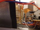
Take a pic from underneath xfmr so we can see windings to the terminal pins

If that confirms wiring locations, it’ll be move wire from pin 4 to unused pin (solder direct to that.)
 
Last edited:
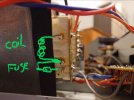
Ok check that coil (primary) has continuity (see pic)

From what I read above it sounds like the primary is open

IMG_6640.jpeg
 
@colegget does your multimeter have a continuity setting? If it does you can see how it should react by setting it to that and then touching the leads together.
 
I just checked my mulitmeter. On the continuity setting it will say 1 when the leads are apart and then when I touch them together it makes a sound and the numbers change (has three numbers in a row).
 
Ok check that coil (primary) has continuity (see pic)

From what I read above it sounds like the primary is open

View attachment 3799947
The two coil ends measure at 1 exactly. Shouldn't it be lower if it's working? For what it's worth, the top end of the coil (picture wise) and the fuse also measure at 1 while the lower end and the fuse are at .3.
 
I just checked my mulitmeter. On the continuity setting it will say 1 when the leads are apart and then when I touch them together it makes a sound and the numbers change (has three numbers in a row).
My multimeter does not beep when there is continuity but if they aren't connected it displays an open loop message and when there touched together the numbers are low (as I would expect).
 
So the coil is at 1 ohm?

And the fuse at 0.3

Try powering on.
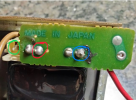
Check for 11V ac at terminals 601 and 602 on top side

Also try it with speaker impedance switch in both modes (I’ve seen these cause chaos)
 
Back
Top Bottom