• The move to the new server is done. There are some software and database maintenance updates in process. This has us passing the hat around to help out. We appreciate any donations. Seriously, even a dollar helps. The payment page may be found here - https://www.audiokarma.org/support.html

Denon DP-47F has two issues after re-capping

Yes, that's the one that you have found, VR1.
Can you access that when the board is mounted or is it on the opposite side facing the platter?
First, (with it unplugged), mark the current position of the VR using a marker. Then, pick a direction (50/50 chance), and turn it a small amount using a small phillips screwdriver.
Next, put it back and plug it in to see if the 45rpm speed has changed for the better.

View attachment 3787229

Unfortunately, the board is screwed in place with 6 screws and the solder side faces me when I open up the bottom. That means platter off, flip it over, remove the board, make the adjustment, screw the board back in, flip it over and test. Granted it’ll take one try at best and multiple times at worst and the prospects of the latter is giving me heartburn. That said, I understand the steps but I’m not sure I’m in a big rush to do it, given the amount of trial & error steps. That’s what I’m weighing as my current workaround works.
 
Well I'd guess that if the VR needs adjustment but can't be reached because the top side of the board isn't reachable, you can release the circuit board, unbundling cables if necessary. The turntable can be the right way up and platter on during testing, it just has to be placed on boards or blocks, high enough to give you enough space to work with the circuit board. The scope test sounds as if you need to adjust the VR while observing the pulse position in relation to the waveform. So it's not remove board, adjust VR by guesswork, screw back together, test. You should see the position change in real time as you adjust the VR, and with a bit of luck, it'll get to where it's supposed to be, as shown in the drawing.
 
Well I'd guess that if the VR needs adjustment but can't be reached because the top side of the board isn't reachable, you can release the circuit board, unbundling cables if necessary. The turntable can be the right way up and platter on during testing, it just has to be placed on boards or blocks, high enough to give you enough space to work with the circuit board. The scope test sounds as if you need to adjust the VR while observing the pulse position in relation to the waveform. So it's not remove board, adjust VR by guesswork, screw back together, test. You should see the position change in real time as you adjust the VR, and with a bit of luck, it'll get to where it's supposed to be, as shown in the drawing.
Oh that’s interesting. Yes, the TT can be elevated up off a tabletop and running for the operation. If I illuminate well and there’s enough clearance for my hands (and there should be), I can incrementally turn VR-1 with a 3” screwdriver. It never occurred to me that I could touch a circuit board while the turntable is powered and running. What precautions do I need to take, if any? This is sounding better! Thank you. PS - since I’m doing this in real time and it’s a trial and error adjustment, this is in lieu of an oscilloscope, correct?
 
I was really talking about the test you'd do with the scope, and perhaps I overinterpreted when you said acquiring an oscilloscope is not the problem. I believe it's still possible to pick them up (analogue) quite cheaply. I paid very little for mine, and they're useful to have around.

You can certainly check a board while the device is powered on, but yes you need to take precautions, not least because even if nothing on a specific board is a risk to your safety, there's still mains voltage coming into the turntable, which you'll want to be very careful around, and you can damage or kill components (or the oscilloscope)if you short circuit something.

As far as precautions go, yes you need to take them with any powered-on device: I can't outline everything from electrical to component safety to DP47F specifics even if my knowledge was more than quite basic, but you'll need to read up on it or view as many videos as you can. And then: very slow and very careful. If you keep clear of the power supply section and caps, the worry for the area of the board you're testing isn't so much shock as shorting and damaging components. But the service manual seems quite clear on what and where to test, so if you're careful to touch those points only, there shouldn't be a problem.

To adjust VRs, I use ceramic adjustment tools for VRs, not metal screwdrivers. Though you'd probably need a set as VRs come in a few slot sizes. Better to use that or a plastic trimmer tool than a screwdriver.
 
Last edited:
This is from the SM.
  • See the note at the bottom of the instructions. The 33rpm is fixed (relative to the 45rpm) by R12.
  • It sounds like the lock adjustment is performed at 45rpm only using VR1. You don't quite get a lock so you might be just beyond the lock range.
  • When you change the speed, you hit the right speed and can get it to lock, then it maintains lock.
  • If you have a scope, then you can check the relationship of the pulse with respect to the ramp according to the timing diagram.
  • If not, you can try adjusting VR1 slightly (one way or the other) to see if you can get it to lock in at 45rpm, then check for lock when you switch to 33rpm
  • If 45rpm cannot lock, then maybe R12 is out of tolerance.
View attachment 3786300
View attachment 3786304
View attachment 3786298
I am finally getting my head around what is entailed here. I cannot identify visually where TP-1 & TP-2 are located on the main board. Can someone help me identify them?
 

Attachments

  • Board.jpeg
    Board.jpeg
    157.7 KB · Views: 11
  • Motor Board.jpeg
    Motor Board.jpeg
    131.6 KB · Views: 9
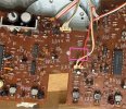
Here it is. Your photo of the area with the test points outlined in pink.
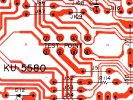
Next, the board layout showing the same test point area, but the picture is flipped so it matches you photo orientation.

Screenshot 2026-06-22 135951.jpg
Screenshot 2026-06-22 140005.jpg

Here is how it is marked in the SM.
Screenshot 2026-06-22 140322.jpg
 
Thank you very much. So the test points are solder mounds, not a pole or something else to grab onto. The oscilloscope probes are alligator clips? There's nothing to grab onto and I only have two hands. Is this a two-person job, I wonder...?
 

Attachments

  • Test points.jpeg
    Test points.jpeg
    174.4 KB · Views: 6
You can temporarily solder a wire to the test point then clip your scope probe to the wire. Remove wire when done.
 
{edited} OK. Understood and Thank you. This will take me a few weeks or longer depending on sourcing a scope. Very much appreciated!
Last question; can you help me identify Terminal 42 on the servo board?
 

Attachments

  • Screenshot 2026-06-23 at 8.17.13 AM.png
    Screenshot 2026-06-23 at 8.17.13 AM.png
    130.5 KB · Views: 8
  • Board.jpeg
    Board.jpeg
    157.7 KB · Views: 6
Last edited:
Can you please check this for me, your photo is too blurry to tell.
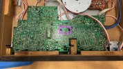
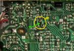
The yellow circle is where VR1 is mounted. The green arrow points to maybe a hole through the PC board to access the VR with a small non-metallic screwdriver? I can't tell.
If it is a hole and the CR has a screw head, you might be able to turn it while the board is mounted.

Screenshot 2026-06-22 161950.jpg
 
Can you please check this for me, your photo is too blurry to tell.
The yellow circle is where VR1 is mounted. The green arrow points to maybe a hole through the PC board to access the VR with a small non-metallic screwdriver? I can't tell.
If it is a hole and the CR has a screw head, you might be able to turn it while the board is mounted.

View attachment 3787697
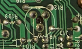
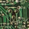
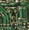
{Edited} There is a hole there and there is something behind it, but it looks like a donut hole and not a phillips or slot for a screw driver. I won't know until I open up the bottom again. That's the best shot I have of the underside of VR-1

I have to right side the TT again to do the VR-1 adjustment [can't do it running the TT upside down or on it's side],
so on stilts, I either let the board drop down and I stabilize it, or work it with my hand up into it to turn the VR-1 from the underside...which still feels awkward as I think it through.
 

Attachments

  • Screenshot 2026-06-23 at 8.46.46 AM.png
    Screenshot 2026-06-23 at 8.46.46 AM.png
    962.7 KB · Views: 5
  • REAR OF BOARD VR1 detail.jpeg
    REAR OF BOARD VR1 detail.jpeg
    26.7 KB · Views: 4
Last edited:
You are looking in the wrong place.
Compare the board layout and location of VR1 against your photo of the back side of the board.
I have marked the location of VR1 with a green circle on both drawings. I tried to matchup the board traces between the two so you could find it.
Your photo does not go far enough to the left to see it.
See if there is a small hole on the trace side of the board in that VR1 location so you can insert a non-metallic screwdriver.
Screenshot 2026-06-22 164304.jpg
Screenshot 2026-06-22 164327.jpg
 
You are looking in the wrong place.
Compare the board layout and location of VR1 against your photo of the back side of the board.
I have marked the location of VR1 with a green circle on both drawings. I tried to matchup the board traces between the two so you could find it.
Your photo does not go far enough to the left to see it.
See if there is a small hole on the trace side of the board in that VR1 location so you can insert a non-metallic screwdriver.
View attachment 3787711
View attachment 3787712
 

Attachments

  • REAR OF BOARD VR1 detail.jpeg
    REAR OF BOARD VR1 detail.jpeg
    26.7 KB · Views: 6
OK. Apologies for the misdirects from me, but I'm all set. I will pick up a 2-channel oscilliscope and access the VR-1 from the underside with a plastic philips driver.
 
I can't see inside the hole. Just make sure that it is a Phillips screw head and that you don't force it to turn. Mark the current position of the screw before you turn it so you can return it to the original position if it doesn't do anything.
 
I can't see inside the hole. Just make sure that it is a Phillips screw head and that you don't force it to turn. Mark the current position of the screw before you turn it so you can return it to the original position if it doesn't do anything.
Understood. Thank you.
 
Unfortunately, the board is screwed in place with 6 screws and the solder side faces me when I open up the bottom. That means platter off, flip it over, remove the board, make the adjustment, screw the board back in, flip it over and test. Granted it’ll take one try at best and multiple times at worst and the prospects of the latter is giving me heartburn. That said, I understand the steps but I’m not sure I’m in a big rush to do it, given the amount of trial & error steps. That’s what I’m weighing as my current workaround works.
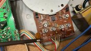
I elevatet the TT on 4 toilet paper Rolls , with bottom off. With careful orientation and safety procedure-live current- you can adjust the right VR with platter spinning & phone app running. I use Shaknspin which makes it much easier
 
I elevatet the TT on 4 toilet paper Rolls , with bottom off. With careful orientation and safety procedure-live current- you can adjust the right VR with platter spinning & phone app running. I use Shaknspin which makes it much easier
Could you recall the type of screwdriver you used to turn the VR1 component from underneath the circuit board? Was it ceramic, plastic, Phillips head, or straight head? Any information you can provide would be greatly appreciated. Alternatively, I may need to purchase a set of ceramic screwdrivers. Knowing the size and type would be ideal. Thank you.
 
Back
Top Bottom