• The move to the new server is done. There are some software and database maintenance updates in process. This has us passing the hat around to help out. We appreciate any donations. Seriously, even a dollar helps. The payment page may be found here - https://www.audiokarma.org/support.html

Denon DP-47F has two issues after re-capping

image.jpg
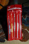
Did not have a a plastic one, which should be used! Used gloves to insulate my self from electrically . Size is one if these, standard flat 2mm/3mm
My .TT is 51F, the VR was not so close to metal trace…
 

Attachments

  • image.jpg
    image.jpg
    94.8 KB · Views: 1
Last edited:
The reason you don't use metal is not because of electrocution, but so you don't damage the variable resistor or so you don't short out something else on the board. First make sure that there is a screw in that hole that you can turn? It might just be a hole.
 
Shrink tubing on the shaft of the driver can help prevent shorts.

An fm alignment kit will have plastic tools.
 
The reason you don't use metal is not because of electrocution, but so you don't damage the variable resistor or so you don't short out something else on the board. First make sure that there is a screw in that hole that you can turn? It might just be a hole.

The more I’m thinking about this project, the more it makes sense to let the circuit board drop down to my table in order to turn the VR with a ceramic driver. I’m wearing rubber insulated gloves, and now the option of top versus bottom access to the VR is moot. I’m working this out in my head and it’s all prep. Opening up the bottom. Releasing the board. Soldering wires to the test points. Setting up the oscilliscope. And look, you said it yourself, “mark the white top of the VR in case I have to revert back and deal with it differently” as that resistor in front of the VR on the board could be the point of weakness and not the VR….
 
Back
Top Bottom