• The move to the new server is done. There are some software and database maintenance updates in process. This has us passing the hat around to help out. We appreciate any donations. Seriously, even a dollar helps. The payment page may be found here - https://www.audiokarma.org/support.html

Denon POA 6600 Thread

Ignore the word Maybank!
OK.

And you can ignore my statement about the missing side brace/bracket. Looking at your photo again I see that it is there. When the PCB is properly positioned it will press against the foam pad on the bracket, there is an indentation in the foam from when the board was there before.

:beerchug:,
James
 
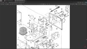
It was this picture from the POA 6600 Service Manual that made me think that mine was normal (see part 25) but I can see there have been variants over time and in different locales.
 

Attachments

  • metalparts.jpg
    metalparts.jpg
    84.3 KB · Views: 3
It was this picture from the POA 6600 Service Manual that made me think that mine was normal (see part 25) but I can see there have been variants over time and in different locales.
None of my 3 amps have that bracket part #25. I have 2 multi-voltage and one 220v model. What I found very interesting was the copper heat spreader on the heat sink of the 220v models, part #62 in that drawing.

If you have not replaced your speaker relays now would be the perfect time when you have that board loose.
This is what I used:
https://www.mouser.de/ProductDetail/Omron-Electronics/G5RL-1A-E-TV8-DC24?qs=TF2qWOo/Jh2DpOurHofHkA==

:beerchug:,
James
 
None of my 3 amps have that bracket part #25. I have 2 multi-voltage and one 220v model. What I found very interesting was the copper heat spreader on the heat sink of the 220v models, part #62 in that drawing.

If you have not replaced your speaker relays now would be the perfect time when you have that board loose.
This is what I used:
https://www.mouser.de/ProductDetail/Omron-Electronics/G5RL-1A-E-TV8-DC24?qs=TF2qWOo/Jh2DpOurHofHkA==

:beerchug:,
James
Thanks I have ordered 4 relays to add to the soldering jobs!
 
And they turned up from Mouser.de at half the height of the originals, but the correct pin layout. Part number 653-G5RL1AETV8DC24 see https://www.rapidonline.com/catalogue/search?Query=Omron G2RL-1-E-24DC SPCO PCB Relay 16A which is what they look like. Any concerns?
Yes, they are short, but they are what I used and my 2 working amps are in daily use with no problems. They are rated at 16 amps on the contacts which is 3+ times the original parts rating.

:beerchug:,
James
 
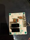
I have now removed the doctored output boards and find mysteries galore. Whoever did that work to upgrade to Michell speaker connectors left the pictured crime scene! They used the edge connections 12-15 on the board to connect to the Michells with soldering that needs cleaning up. But the board has none of the components on the front of it, can you confirm that is right, because if you look at the rear, it does look wrong. The connectors you suggested I buy are to be soldered back into holes on the middle of the board.
 

Attachments

  • 20240826_151247.jpg
    20240826_151247.jpg
    100.2 KB · Views: 10
  • 20240826_151306.jpg
    20240826_151306.jpg
    107.8 KB · Views: 9
I have now removed the doctored output boards and find mysteries galore. Whoever did that work to upgrade to Michell speaker connectors left the pictured crime scene! They used the edge connections 12-15 on the board to connect to the Michells with soldering that needs cleaning up. But the board has none of the components on the front of it, can you confirm that is right, because if you look at the rear, it does look wrong. The connectors you suggested I buy are to be soldered back into holes on the middle of the board.
Ouch. If my eyes are not deceiving me they snipped off all of the jumpers from the front side and left the ends still soldered to the board?

I kind of messed up concerning taking photos of those boards and have no good photos of the front side.
Here is one not so great photo with the board in place with the new binding posts but with the original tall Omron relays.
DSC01635.JPG

And here is one with the board removed while I was working on the PSU board, it has the new short relays installed at that point.
DSC01819.JPG

What I am going to have to do is pull my 3rd amp down from storage and pull that board and take some good photos for you. It also has some small aftermarket posts on it but I
don't think that it has been forcibly raped.

This may take a day or 2. Lucky for you my sore back has improved to the point where I think that I can get the amp down without a problem.

:beerchug:,
James
 
Crime scene, even rape, I believe you! I am very grateful for your help and might help with the service manual, but it is too large to attach. Do you need it to know values? Bizarrely the amplifier was working before for the last two decades. This component loss must have caused some grief? The only reason for starting this 'repair' was because the terminals started rotating when used and I could see the connectors about to short to chassis, with bit of plastic/nylon that had fallen off.
 
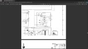
The output board is very simple in the Service Manual (the board seems to have components no longer needed). You can also see the terminals 12-15 on the right here to the speakers. 9117-5 output-board.jpg
 
Crime scene, even rape, I believe you! I am very grateful for your help and might help with the service manual, but it is too large to attach. Do you need it to know values? Bizarrely the amplifier was working before for the last two decades. This component loss must have caused some grief? The only reason for starting this 'repair' was because the terminals started rotating when used and I could see the connectors about to short to chassis, with bit of plastic/nylon that had fallen off.
I have a good copy of the SM that I bought from Norm at Analog Alley.
https://www.analogalley.com/osccart/login.php?osCsid=d972f3525bc11d49e77cb487bacd489f
It's a black&white pdf but much better quality than the others that you can download. No affiliation, but it was well worth the small price.

:beerchug:,
James
 
The posts that they used do connect directly to the speaker relays. With no binding posts connected to the original pads I don't see the reason for cutting the jumpers that led to the original plus terminal pads. It looks like the coils and resistors are still in circuit and functioning.

Replacing the jumpers with some 0.8mm wire, removing the wires from your existing binding posts to those upper posts, and installing the new binding posts should restore things to original without too much problem.

I just remembered that I have another set of new terminals from Speaker Terminal. I'll take a few photos of them tomorrow so that you can get a good look at them.

:beerchug:,
James
 
Last edited:
Many thanks for the link, it is worth the money (although I am not an electrical engineer) and have bought it. Also thanks for the relief in your explanation. My new speaker terminals are in transit from near Zurich to me in Devon. I have a graduate electrical engineer lined up to do the necessary fixes! I was beginning to think I had to use the edge connector pins again to the new speaker connectors using crimp blades or something. I cannot believe how close that wiring was to be a short across pins 10, 11. I was extremely lucky. The final mystery seems to be C702 C703 that are missing from the board, but shown in the circuit. Can you see if you have them and what values?
 
Last edited:
Many thanks for the link, it is worth the money (although I am not an electrical engineer) and have bought it. Also thanks for the relief in your explanation. My new speaker terminals are in transit from near Zurich to me in Devon. I have a graduate electrical engineer lined up to do the necessary fixes! I was beginning to think I had to use the edge connector pins again to the new speaker connectors using crimp blades or something. I cannot believe how close that wiring was to be a short across pins 10, 11. I was extremely lucky. The final mystery seems to be C702 C703 that are missing from the board, but shown in the circuit. Can you see if you have them and what values?
Not all components are installed in every model. It could easily be that those 2 caps were never used in your model of amp. My 3rd amp a is a straight Europe model, I will look at what is installed in it.

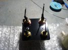
It seems that ZZ Top is done playing in my living room tonight and I had enough time to take some photos of the new terminal blocks just now.

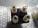
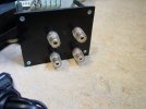
They are nicely made. The terminals themselves are the same 5-way posts that are very popular and I use them a lot. I use Cardas spade lugs on my speaker wire and they fit nicely on these posts.
They are mounted on a 3mm thick piece of phenolic or PCB material, 57x57mm. The mounting holes have a threaded tinned metal through hole insert and come with mounting screws.
The connection wires are solid core, flattened on the ends to fit exactly into the PCB slots and have shrink wrap covering the ends of the posts.

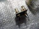
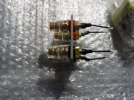
DSC03022.JPGDSC03023.JPGDSC03025.JPGDSC03027.JPG

When I ordered mine I made a thinking error and ordered "2". Because I assumed that they were selling one terminal block for one monoblock. But it seems that these people are clever enough to know that most people use 2 of the monoblocks so I ended up with a total of 4 of these binding posts. :biggrin:

When you install them make sure that the through holes are free of stray solder and push them in until the leads are up against the non flattened part of the lead. They will then be a perfect fit.

:beerchug:,
James
 
Ok, here are photos of the speaker terminal board from my 3rd amp. My first 2 are multi-voltage models and are a bit different from the other models but this one is a European 220v/50hz model.

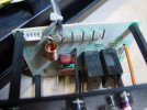
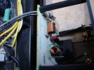
Someone has replaced the terminals with ones that are similar in style to my new ones but smaller. The solution is nicely done, with a 2mm plastic board for the terminals and plastic stand-offs securing it to the PCB.

DSC03028.JPGDSC03030.JPGDSC03031.JPGDSC03032.JPG

So we can see that C702/C703 are not populated on this board.
DSC03033.JPGDSC03034.JPG

:beerchug:,
James
 
So, an update.

I deliberately only replaced one set of op-amps previously, IC501 (in the idle current section), it seemed best to to not replace IC502 at the same time if I wanted to be able to hear any potential differences.

The amps have been sounding great so far. And in the meantime I have been doing some thinking about op-amp choices.

Using the OPA1656 in the IC501 position seems like a bit of an overkill, with it's 100mA of output current being wasted there. However, the M5218 in IC505 has 50mA of output current, and the 1656 is the only part that I have on hand that meets or exceeds that. And the OPA1642 nearly matches the idle current draw of the original NJM082 parts while still having a bit more output current.

So I soldered up a pair of OPA1642 parts to try out in IC501, with the plan to move the OPA1656 to IC502.
I made that swap today.

Before putting the amps back in the rack I checked voltages. The supply voltage rails to the op-amps did not change, remaining at +/-15.1v. The idle current voltages did not change with the new op-amps, remaining at 8mv with a slow fluctuation of about +/-0.2mV. The DC offset was 6mv left amp and 2mv right amp before the swap, with a fluctuation of about +/-0.2mV. This remained the same after the swap.

My expectations were that I did not expect any change to speak of. My expectations were wrong.
My immediate impressions after one CD (all that I have listened to so far) is that the highs are improved, vocals are clearer and more understandable, and there is more depth to the soundstage.

Now that I have posted this I am going to go back and spin some more disks and explore this change.

:beerchug:,
James
 
OK, so here is a thought.

If you are replacing IC502, and are installing an op-amp on/with an adapter board with exposed leads like the one that I have, Don't do it with your left hand while your right hand is grounded to the case.

Because when I did that (and yes, the amp was unplugged from the mains, I am not that stupid), I discharged something.
Through... ...me!
And from the amount of juice I am guessing that it was all 4 main filter caps (10,000µF x 4).

It was... ...uncomfortable(!)... ...and at the same time... ...breathtaking(!).

I can state with conviction that you do not want to do this. :biggrin:

:beerchug:,
James
 
Back
Top Bottom