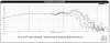
Looks like you're rapidly gaining insight into the fundamentals of a 1st order network. Hafta agree with
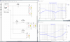
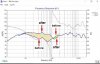
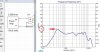
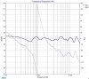
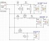
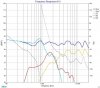
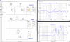
@elnaldo that performance will likely suffer from a 10dB depression in the midrange. Assuming you're still using 8Ω GM-85/8 drivers, I'm curious why you have them wired in series for a 16Ω load rather than parallel for 4Ω. That alone reduces relative output level. You could try setting them in parallel in Xsim just to see how that compares
:
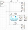
View attachment 2526049
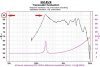
"Tune" values of C2 and L1 as shown above to set bandpass crossover frequencies similar to where they are in the series configuration. Those corner frequencies appear to be roughly 250Hz on the high pass side (capacitor) and 2800Hz on the low pass side (Inductor), based on factory published impedance curve. Though actual driver samples may vary.
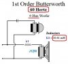
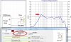
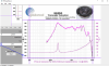
I'm also curious about the woofer inductor value, which seems high for a 4Ω woofer. Big woofers with their large, inductive voice coils typically have a rapidly rising impedance shortly after resonance. Published resonant freq. for Jensen J12W is 30Hz. If impedance settles back down around 4Ω by 60Hz before it's inductive climb, then crossover frequency could actually be that low, or thereabout
:
View attachment 2526075
So another thing you could experiment with is tuning that inductor value down to see if it adds more energy higher up in the bass region.
Xsim is an excellent tool for delving into this subject. Some expert members here appear able to master this stuff in their sleep. For the rest of us, it's fun to work up a circuit from what we think we know of theory, then watch the results inexplicably defy reason.
It's all about the learning!