• The move to the new server is done. There are some software and database maintenance updates in process. This has us passing the hat around to help out. We appreciate any donations. Seriously, even a dollar helps. The payment page may be found here - https://www.audiokarma.org/support.html

Diagnosing a mute MC2300?

Johnny_Law

o.O
Subscriber
McIntosh gurus,

I recently acquired a studio-abused MC2300 without any pc boards. I purchased new circuits directly from McIntosh (part# 04424300, from Brian Scott in McIntosh Customer Service Parts Department). I installed the boards but alas, no sound.

The unit turns on and lights up and the fans come on. Just no sound. Inputs had been modified sometime in its earlier life from RCA to 1/4".

Serial # is 2Y371.

Despite paying a chunk of change for it, I'd like to repair it instead of return it. Currently running a C24 into an MC502 and enjoying the prospect of getting the MC2300 running, especially with ML-2Cs waiting to go into my rotation. :)

In any event I'd love any tips / tricks about where to start the diagnosis and namely if this is a common issue with the MC2300.

Much appreciated,
Ryan

Threads I've found & read thus far:
http://audiokarma.org/forums/index.php?threads/mc2300-in-the-hospital.620631/
http://audiokarma.org/forums/index.php?threads/mc2300-serious-bidness.621567/
http://audiokarma.org/forums/index.php?threads/mc2300-issues.461972/
http://audiokarma.org/forums/index.php?threads/calling-all-1yxxx-serial-number-mc2300s.320290/

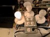
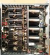
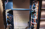
And I couldn't help but snap a pic while waiting for the boards to come in:

C0FKhQZ.jpg
 
Last edited:
Register to hide this ad
If the amp was missing the driver boards, have you inspected it for other missing or disconnected components? The output devices plug into male push on strips located on the underside of the chassis - grouped by each of the 8 heat sinks. Remove the bottom cover and you'll see these behind the filter caps.

If you see things disconnected, it may be for a reason ...
 
Obtain a copy of the service manual. The signal path is pretty straight forward. The Stereo/Mono switch on these amps (rear panel) is a maintenance item as they do require periodic cleaning. It is in the signal path so you want to be sure it's cleaned and working.

I have seen an MC2100 with the very same problem you report. It turned out that both gain pots had suffered an impact and wouldn't pass signal. I bypassed them with alligators as I waited on replacements.

Short of this simple stuff, you may elect to have it serviced by a qualified tech.
 
You should check the fuses too with emphasis on pwr supply fuses.. Sometimes a fuse will look good but still be the culprit. Use a meter to check for continuity. Or according to the old axiom, "In for a penny, in for a pound." Replace all fuses.
 
Going back to my scholastic book club days, what were they, encyclopedia brown, Emil and the detectives, the Hardy boys........sometimes repair work demands careful, basic detective work.

Why would someone pull the boards? Did they scavenge anything else out of the amp? Are there voltages in the correct places?

I would leave your newly purchased boards out of the amp to be sure you do not smoke them as you do these basic tests.

I would guess they burned the crap out of the driver boards by having a wholesale failure of output transistors. No need to put at risk your new boards.

A recent post from a tech looking for a bridge rectifier highlighted his client's reluctance in correctly repairing a MC2300 as his client faced the reality that his pursuit of Garcia would be costly.
 
Thanks all! A basic fuse check / diagnosis / circuit check is of course on the calendar - I was more trying to ask whether there are any common / frequent MC2300 issues resulting in a mute unit. Whether or not there are issues so common you could say "oh, no sound from an MC2300, that happens all the time, it's gotta be ______!" But I suppose if the MC2300 doesn't have common quirks like that, even better, and a testament to solid engineering and manufacturing!

The history of the unit is indeed curious, as the story goes, it was bought and put into service in a recording studio in San Francisco. The studio had the RCA inputs converted to the 1/4" inputs. At some point, somehow it blew one pc board in the 80's and a shop somewhere began to repair it when the studio went out of business and shut down. There it sat in a storage unit for decades until the owner finally decided not to re-open the studio and to liquidate all the gear. As I dig into this thing, the story may unravel or not ... we'll see!
 
Last edited:
The early RCA driver transistors on the boards failed too often in commercial use so Mac did a upgrade back in the late 70s. That upgrade was followed with a further driver transistor upgrade in the 80s. This final upgrade was a must do whenever one of these amps would come into a clinic. When the drivers would fail too often the outputs would follow cascading the issue.

I would start pulling heatsinks and at this point and see how many output transistors are shorted. Would not be surprised if you would need all 24, in fact to do it right for the future.......Just make sure to use inductive wirewound resistors from Mac and if you have a high frequency oscillation still Terry has a interesting solution.
 
Finally coming back to this. First time working on my MC2300 since 2016.

Have learned a lot in the last 4 years - and continue to learn - hopefully in a better place now to understand how to get this up and going. Very sad to hear of @c_dk passing, thankful that he helped me. RIP.

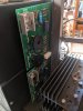
Some pics. First, here are those new output boards I ordered new from McIntosh back in 2016 (yes those NTE are straight from McIntosh :eek: ):

PXL_20201129_214413910.jpg

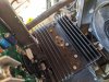
Anyway, so back to diagnosis mode. I started by plugging it into my DBT, and the bulb was very bright while the meter lamps did not illuminate. Maybe this was just because the massive filter caps were consuming so much current, but I decided to start by checking for shorted OPTs. So I pulled all heat sinks (except for the inner two) - all outputs test OK. However, the three on one heatsink had been replaced with 2N3055s (which also test OK) but I will probably try to find three 032-070 to match the other 21.

I managed to remove 6 of the head sinks but got stuck on these. How does one remove the inner two heat sinks? They have things attached to them that prevent them from being removed. I suppose that's the answer but wanted to make sure.

PXL_20201129_214523303.jpg

I also found evidence of previous work that I'd like to run past everyone.

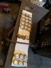
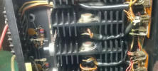
OPT collector insulators - I found some, but not all, of the middle OPTs had an insulator below them. The service manual is silent as to insulation. Do all middle OPTs get insulators, or just some?

These two had no insulator under the middle OPT:

PXL_20201129_215119127.jpg

If the collectors on the middle OPTs here were shorting to ground, maybe this explains the bright bulb.

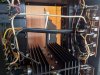
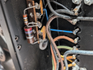
The last oddity I noticed is what appears to be a solid gauge wire soldered to the 1ohm output tap from both output transformers, you can see the dark blue wire appears to be there but cut. Is this factory / normal / correct? Or is this someone's hack job? Check out the white wire:

PXL_20201129_214351774.jpg

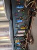
From here, I'll put it back on the DBT to make sure there's no other shorts, then I'll see how the power supply is doing. Hoping the can cap is doing OK. Will be ordering new caps for the intake and meter boards, hoping Nichicon ES / KT radial leads will reach the axial config. Also ordering WIMA MKS4 to replace C9 and C10. The caps in C9 and C10 now aren't original, they look like they could be tantalum? The green ones that look like little drops:

PXL_20201129_215034918.jpg
 
Last edited:
Plugged into the wall, power supply voltages all 100% correct.

Fans working great pretty much silent, blowing air OUT and not in.

Half the bulbs are dead, easy fix.

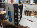
PXL_20201130_003552903.jpg

Next up is to check all the emitter resistors... and figure out how to re-install all of the OPTs (with or without mica or other insulators).

PXL_20201130_003856917.jpg
 
The heatsinks are hot, and it is correct that only a few OPTs are insulated.

My experience with this model is the 2105 which is basically half of a 2300’s output circuitry, and on the 2105/2100 you can look at the schematic and see which cases are powered / tied together by the heatsink. Note also that when re-installing the heatsinks are electrically insulated from the chassis.
 
When getting ready to power up again on the DBT, you can do so without the driver boards plugged in, which will show you what the normal bulb reaction is to charging the PS caps. I would do this first, then install OPTs and resistors, can do this a channel at a time and test if all goes well install and test with driver boards one channel at a time. I would do all testing in 2-channel mode before doing anything with mono mode.

Also I’m a believer in replacing all transistors, I very much doubt that there is any match between them and since the 2300 relies heavily on current-sharing between transistors (even moreso in mono mode) it is my experience that mismatched OPTs pushed at all will stress them and quickly lead to a failure. The driver boards are NLA, so transistors are a good investment IME/IMO.
 
Thanks! Have plugged it into the DBT with no OPTs installed, now have a frame of reference. The bulb is pretty bright, the meter lights are low and the fans spin slowly. I'll look for the same behavior when the OPTs are back in.

On the insulators, duh, I should have realized the info IS in the service manual, it just doesn't hold your hand to figure it out. Page 8 of the PDF shows the output section, and certain sets of three collectors are all directly connected (two middle on each channel) while certain others aren't (two middle on each channel). So only two of the four heat sinks on each channel are hot with +40V; the other two heat sinks on each channel run the negative 40V rail into the emitters.

Interesting to know about the 2105. I actually have a 2105 on a shelf in the garage as well, bought with a report of "blown outputs" and haven't had a chance to dig into it yet. (why do I keep buying broken amps?!) Lessons here should help me there, I hope.
 
The 2105 has the same driver boards, although your 2300 boards are the latest revision, there are two different P/Ns that I know of and several different schematics just for the driver boards!

If the 2105 has blown outputs, it is likely that you will be repairing the driver boards (not that again!). Pretty simple amps really.

From memory, I believe I was able to operate the 2105 on a 60W bulb, the 2300 will likely need a 100W or more to get up to a voltage where it will charge-dim. You might want to play with bulb wattage before getting too much installed.

My DBT (never heard of one before this forum) is switchable and allows me to add bulbs and with 40/60/100 can run all in parallel for 200W equivalent, can also turn off and bypass, really makes this rebuild thing easy. I recommend building one if you're going to do this a lot with higher-power amps (put in 3 200s if you want!). MC2105 on the bench.dbt.jpg
 
The 2N3055 do not belong in there. The original transistors are obsolete and replaced with onsemi MJ15003G. These are used in the 2100, 2105 and the 2300. When testing make sure the heatsinks are isolated from the chassis. As said above they carry voltage at high current. As far as the insulators, only 2 outputs in each channel are insulated. They are on the center transistors. If you have the service manual they are Q121 and Q133 in one channel and Q122 and Q134 on the other channel.
 
Last edited:
Have discovered that somebody bypassed the meter boards & autoformers for the 1ohm outputs. These white wires are solid wires soldered directly from the OPT output to the 1ohm taps! The blue wires from the autoformers are cut. Luckily the autoformers are still OK, at least all coils measure continuous, even the cut 1ohm outputs.

Why would someone bypass the autoformers??? What benefit of driving speakers directly from the OPTs?

PXL_20201205_211642363.jpg
 
Who knows. Maybe they thought the amp would sound better direct coupled and they just used the 1 Ohm tap as that connection point.
 
:bye: Hi guys - I never figured this thing out and have been lugging it through various moves, mounted in a beat up rack on casters, it survived a 3 foot fall from a u-haul ramp and ... it's back on the bench! I'M GONNA FIGURE IT OUT THIS TIME! :rflmao:

1772415771777.png

Quick question: the thick white wires I identified above ...

I removed them but ... upon closer inspection ... I am wondering if, in fact, the white wire is needed?

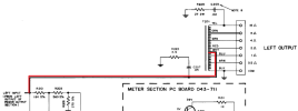
My theory is, it is the white wire in this part of the schematic (which I've used my best MS Paint skills to highlight in red):

1772415283675.png

I can't see ANY other white wire in mine that goes from the output of the power amp section to C207/R225.

Take a look (the thin blue wire comes off the 1ohm tap and goes to the cap/resistor in the picture, while you can see the thin yellow wire going from the 16ohm tap to C205/R223) - understanding that the thick wire from the autoformer to the 1ohm tap is still cut, same as above, I haven't soldered it back in place yet):

1772415344678.png

THEN, I've looked at other MC2300 pictures online and it definitely looks like there's a second thin - white - wire leading to the 1ohm tap ... see e.g. McIntosh MC2300 Vintage Stereo Power Amplifier (serviced & recapped) - Photo5139508

In the red boxes I drew, you can see the thin red wire on the 1ohm tap!

fds.jpg

I don't have such thin white wires ANYWHERE ...

So - my theory is, I should leave these white wires in place.

Can anyone confirm or refute the presence of such white wires in MC2300s normally?

THANK YOU! LET'S GET THIS THING GOING THIS TIME! IT'S BEEN 9.5 YEARS! I'M AN OLD MAN NOW!
 
Hmmmmmm ... the plot thickens.

I tried to watch some YouTube videos to see if I could find a good view of the output terminal wiring.

From this video ... not seeing a white wire to the 1ohm tap:

1772478428414.png

Not this one either:

1772479131476.png

Or this one:

1772479307631.png
 
Last edited:
Back
Top Bottom