FYI Purchased a brand new in the box MC2300 in 1978. After a decade the resistor on the output card drifted and blew up the amp on that channel. I replaced the big 39,000 caps with new ones and all the output transistors with new OnSemi-15003g. I ordered new cards from McIntosh and luckily have a Staco Variac with a 2 amp fuse as a slowly brought up the voltage the 2 amp fuse blew. I called McIntosh parts to tell them what happened and they told me to ship back the 2 new cards. They returned them repaired new and said someone at the factory put in the wrong transistors on the board. Now the amp runs like it should.


You are using an out of date browser. It may not display this or other websites correctly.
You should upgrade or use an alternative browser.
You should upgrade or use an alternative browser.
Diagnosing a mute MC2300?
- Thread starter Johnny_Law
- Start date

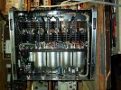
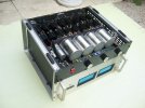
I also replaced the electrolytic caps on the input board. It greatly improved the sound. The amp puts out almost 400 watts per channel, clean sound. Enjoy your journey as it was fun for me.FYI Purchased a brand new in the box MC2300 in 1978. After a decade the resistor on the output card drifted and blew up the amp on that channel. I replaced the big 39,000 caps with new ones and all the output transistors with new OnSemi-15003g. I ordered new cards from McIntosh and luckily have a Staco Variac with a 2 amp fuse as a slowly brought up the voltage the 2 amp fuse blew. I called McIntosh parts to tell them what happened and they told me to ship back the 2 new cards. They returned them repaired new and said someone at the factory put in the wrong transistors on the board. Now the amp runs like it should.

Solved ... and DEFINITELY not what I was expecting.
Because I did not have the FAN circuitry connected when diagnosing the L channel, the transformer somehow wasn't getting enough current to drive the outputs.
Very weird.
But the good news is that both channels are working great (with the fan circuit connected)! I can only run them one at a time, because I still need to order the replacement Q113, the out-of-the-box-bad new 2N5679, for one of my driver cards.
So in sum, after all that, the only problems were:
-Autoformer bypass jumpers had to be removed
-3 random incorrect replacement OPTs had to be replaced, so I used new MJ15003
-One brand new McIntosh driver card was bad because of a bad 2N5679
-Meter lights replaced with LEDs
Additional observation:
-The fan circuit has to be fully intact in order for the unit to work correctly
-At least one channel at a time, the unit will function and play music at reasonable volume through a DBT
I'll get that transistor on order, in the meantime, I'll listen to one channel at a time on my workbench to celebrate!!
Right channel playing:
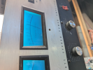
Left channel playing:

Woohoo!
Because I did not have the FAN circuitry connected when diagnosing the L channel, the transformer somehow wasn't getting enough current to drive the outputs.
Very weird.
But the good news is that both channels are working great (with the fan circuit connected)! I can only run them one at a time, because I still need to order the replacement Q113, the out-of-the-box-bad new 2N5679, for one of my driver cards.
So in sum, after all that, the only problems were:
-Autoformer bypass jumpers had to be removed
-3 random incorrect replacement OPTs had to be replaced, so I used new MJ15003
-One brand new McIntosh driver card was bad because of a bad 2N5679
-Meter lights replaced with LEDs
Additional observation:
-The fan circuit has to be fully intact in order for the unit to work correctly
-At least one channel at a time, the unit will function and play music at reasonable volume through a DBT
I'll get that transistor on order, in the meantime, I'll listen to one channel at a time on my workbench to celebrate!!
Right channel playing:
Left channel playing:
Woohoo!
For reference, here's it playing (on just one channel) via DBT with a 100W bulb into a little 8ohm Polk RM101 speaker via the 8ohm tap:
Another oddity I've noticed, though, is that if there is an input signal present when powered on, it won't come up to power fully (it'll put out sound but VERY quiet). To fix it, I need to turn off the input signal and then power it on. Almost as if some kind of relay is tripped. Is that normal (I assume no)?
Last edited:

@Johnny_Law Glad you got it working! Great unit!
I am not an EE - I am a hobbyist - a tinkerer - a hack some would say - LOL - although I do work neatly and do not take shortcuts when working on gear. Here is my take on the subject:
Your basic Variac only varies voltage. Mine has a 10A fuse. Before I had a DBT I would use the Variac with a fuse that was slightly lower than the Device Under Test if I had no background on the unit and feared a short. Some Variacs have an amp meter which I guess can be carefully watched while the unit is brought up to voltage. A true dead short however will blow the fuse on a variac even at the lowest voltage settings. If the fuse is 10amp that energy can damage parts inside the unit before the fuse blows even when a small voltage is dialed in. Both are great to have. These days I use both on an unknown unit for the first powerup and then I use the DBT for subsequent startups between part swapping.
DBT is also great to have when testing hot with a multimeter. If you accidentally short something with your leads the current will quickly be controlled. Your readings will be slightly off but it can provide some safety.
You are right - DBT is not really test equipment, but it is a cheap piece of safety equipment for the hobbyist that also provides some useful visual feedback.
As far as spending more money goes - don't worry - I have a test equipment wish list that will never be fully satisfied - LOL. Next up for me is a better power supply and something to test THD with.

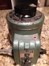
I must have lost this thread or I would have responded to this question. You always have good input on the site, Jose.Refugee, since you are first, how is a Variac not a current limiter? I prefer the Variac because I can increase the Voltage gradually which helps to prevent any large initial current draw that can damage the amplifier. I can raise the Voltage slowly and increase it to a point where I can see it stable and prevent damage. This method is far better than allowing the inrush current to be great enough when the filament resistance is cold and allowing that brief, but large current flow to do damage and realize it is too late.
Dim-bulb testers are for hobbyists. You should do things correctly and spend a little money when you have a lot invested in your equipment. Take it from a retired EE who had has had his hands on designs I know you have touched, seen or heard.
I am not an EE - I am a hobbyist - a tinkerer - a hack some would say - LOL - although I do work neatly and do not take shortcuts when working on gear. Here is my take on the subject:
Your basic Variac only varies voltage. Mine has a 10A fuse. Before I had a DBT I would use the Variac with a fuse that was slightly lower than the Device Under Test if I had no background on the unit and feared a short. Some Variacs have an amp meter which I guess can be carefully watched while the unit is brought up to voltage. A true dead short however will blow the fuse on a variac even at the lowest voltage settings. If the fuse is 10amp that energy can damage parts inside the unit before the fuse blows even when a small voltage is dialed in. Both are great to have. These days I use both on an unknown unit for the first powerup and then I use the DBT for subsequent startups between part swapping.
DBT is also great to have when testing hot with a multimeter. If you accidentally short something with your leads the current will quickly be controlled. Your readings will be slightly off but it can provide some safety.
You are right - DBT is not really test equipment, but it is a cheap piece of safety equipment for the hobbyist that also provides some useful visual feedback.
As far as spending more money goes - don't worry - I have a test equipment wish list that will never be fully satisfied - LOL. Next up for me is a better power supply and something to test THD with.
Solved ... and DEFINITELY not what I was expecting.
Because I did not have the FAN circuitry connected when diagnosing the L channel, the transformer somehow wasn't getting enough current to drive the outputs.
Very weird.
But the good news is that both channels are working great (with the fan circuit connected)! I can only run them one at a time, because I still need to order the replacement Q113, the out-of-the-box-bad new 2N5679, for one of my driver cards.
Spoke too soon. Ugh.
New 2N5679 came in, installed it. Didn't fix it. Same bright bulb.
Figured since I had one working card, I could swap components one by one between cards and see what would fix it.
One by one, I swapped every single transistor from one to the other, aside from Q111 & Q113, checking to see if it was fixed each time. Nope.
At that point I had cleared Q101, Q103, Q107, Q109, and Q105 after swapping them between cards.
Then I decided to try swapping Q113 ... and all of a sudden the good card stopped working. Bright bulb.
Swapped Q113 back. The good card STILL doesn't work. Tried every combination of Q111 and Q113 in the previously good card, but nothing works.
So now I have TWO broken cards, and NO bad devices in either.
At my wit's end for the moment.
Very annoyed that these brand new cards from McIntosh are giving me problems. And annoyed I didn't try them out for years after I got them - so I'm sure McIntosh wouldn't send me replacements at this point.

damacman
Resident Psycho
I gave up on my McIntosh reissue driver boards and sold mine on eBay. I bought mine in 2009 - seems like Gail assembled them.Spoke too soon. Ugh.
New 2N5679 came in, installed it. Didn't fix it. Same bright bulb.
Figured since I had one working card, I could swap components one by one between cards and see what would fix it.
One by one, I swapped every single transistor from one to the other, aside from Q111 & Q113, checking to see if it was fixed each time. Nope.
At that point I had cleared Q101, Q103, Q107, Q109, and Q105 after swapping them between cards.
Then I decided to try swapping Q113 ... and all of a sudden the good card stopped working. Bright bulb.
Swapped Q113 back. The good card STILL doesn't work. Tried every combination of Q111 and Q113 in the previously good card, but nothing works.
So now I have TWO broken cards, and NO bad devices in either.
At my wit's end for the moment.
Very annoyed that these brand new cards from McIntosh are giving me problems. And annoyed I didn't try them out for years after I got them - so I'm sure McIntosh wouldn't send me replacements at this point.

Are you sure these cards are making good contact with the edge connectors? I know I asked you before, but this is exactly the type of frustrating inconsistency I experienced with my 2105. I used a couple of small picks to bend the edge connector tabs to increase their bite on the boards and I have been good ever since.
Do you have a component tester? Can you test these transistors that you’ve been swapping? Maybe at least a 6-way diode check with a meter? I would try to start ruling things out methodically. Start making a list of any parts that you know are good and eliminate them.
Any chance that you got the pinout mixed up on q113?
Do you have a component tester? Can you test these transistors that you’ve been swapping? Maybe at least a 6-way diode check with a meter? I would try to start ruling things out methodically. Start making a list of any parts that you know are good and eliminate them.
Any chance that you got the pinout mixed up on q113?
Last edited:

What is bad about the new circuit boards? Are they Mc parts or aftermarket? I have read on the forum both being used at some point.
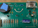
Alright guys. Solved solved now - @Motnick, thanks, you nailed it. While I did read your old post and also confirmed that yes, occasionally my boards have sketchy contact with the sockets ... turns out, the new boards have incorrect silkscreening for the orientation of Q113.
The board:
The correct orientation per the manual:
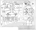
Flipped both Q113s around, and we're back in business for real this time!!

The board:
The correct orientation per the manual:
Flipped both Q113s around, and we're back in business for real this time!!
I suppose for posterity's sake I should note also that C101 in the new boards, a 330uF spec cap, both measured around 560uF on my meter (!). So I replaced them with new 330uF / 6.3V Nichicons (as you can see in my pic above).
Thinking about the driver cards in those sockets ... how are these supposed to be fixed in place? Are they?
I see a threaded standoff behind each one, but no obvious means to attach the boards to them.
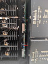
From pics I've found online, it looks like something screws into that. Can anyone tell me what it is?
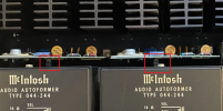
Thinking about the driver cards in those sockets ... how are these supposed to be fixed in place? Are they?
I see a threaded standoff behind each one, but no obvious means to attach the boards to them.
From pics I've found online, it looks like something screws into that. Can anyone tell me what it is?
Inside making music! Sounding great with my C39.
Still need to figure out how to screw down the driver cards, but should be fine as it sits there.
Very happy to have finally fixed it!! It was worth the wait!

Still need to figure out how to screw down the driver cards, but should be fine as it sits there.
Very happy to have finally fixed it!! It was worth the wait!
Yeah - I'm looking! Hard to find.Now she needs a set of handles at least.

Bill Ferris
Lunatic Member
As Monty Hall would exclaim as the host of the game show: the Price is right: Let`s Make a Deal !Boy those'd look nice on my amp!
An A/K PM between youse guys might be in the near future. Yes/No ?

That's OK Heather, thanks, hopefully we can figure out the misfire about the handles.
As I had also mentioned - I was very happy yesterday to confirm that the fans work! I had it playing all day, and by the afternoon it got warm ... I heard a new hum I wasn't familiar with between tracks, it was the fans! Correctly turning on appropriately with temperature, correctly blowing air out vs. in ... so I can check that off the list!
In the meantime, continuing to love this amp. Dug out my JBL 4301Bs which I put on stands, and they sound great. I'm a happy camper!
As I had also mentioned - I was very happy yesterday to confirm that the fans work! I had it playing all day, and by the afternoon it got warm ... I heard a new hum I wasn't familiar with between tracks, it was the fans! Correctly turning on appropriately with temperature, correctly blowing air out vs. in ... so I can check that off the list!
In the meantime, continuing to love this amp. Dug out my JBL 4301Bs which I put on stands, and they sound great. I'm a happy camper!