• The move to the new server is done. There are some software and database maintenance updates in process. This has us passing the hat around to help out. We appreciate any donations. Seriously, even a dollar helps. The payment page may be found here - https://www.audiokarma.org/support.html

dumptruck is finally building ewaves for real

I have not done it yet, but I always assumed you keep the measurements with full "flight time," don't create zero phase versions. That would keep the phase relationships consistent. Sounds right?

I think you don't need the protection cap if you can guarantee no turn-on transients. Or any other glitches. I always assumed the cap would not make any difference in how PCD sees your measurement result because a cap does not add phase delay. But is that true?
 
I realized that to flush-mount these woofers (which gives the closest z-axis alignment) I'm going to need a fully double-thick baffle, which is problematic for my cabinets. Does the crossover tilt the forward lobe up, or down?
 
What do you mean by double thick? as in how thick do you need the baffle to be? Mins is 3/4" with the TD, and its just fine.
 
What do you mean by double thick? as in how thick do you need the baffle to be? Mins is 3/4" with the TD, and its just fine.

Two layers glued together, 1.5". Fairly common to do in subwoofer builds both for stiffness and for added strength when the driver is inset and routing out the recess for the woofer inset leaves a somewhat thin mounting flange.
 
Last edited:
Yeah, simi yours are rear-mounted. I wanted to mount it from the front to get it closer to alignment with the CD, but the frame is too thick to flush mount in 3/4". I think what I'll do is mount it from the rear but inset a bit, and see what I get.
 
Ah.. ok, I understand now.. but I kinda think you're taking it a little too far? I did recess my horn, which pulled the CD closer to alignment, but I only did that because I didn't have room between the baffle and grill.

But when you're talking you're sitting 10 feet away from your speakers, and only talking being maybe 1/2" to 2" out of alignment, you'll NEVER hear that kinda difference. The amount of time it take that HF to get there compared to the LF to get there, it's really a pretty much moot point. Sounds travels pretty fast, especially when you're talking about 10 feet and an inch or two.

I'd bet that if you could hear a 2" misalignment in speakers from 10 feet, you've got the most sensitive ears on the planet.. for a human.

The majority of speakers out there on the market, and ones that have been sold over the years are way further off in alignment than what you'll be sitting at..
 
Last edited:
A big part of this whole design concept is that you design for flat response on the axis of the primary lobe - that's how you end up with those tidy polar plots. When you move one driver forward and backward, you are aiming the lobe up and down. If you picture an imaginary string between the centers of the voice coils of both drivers, the change in angle of that string when you move the drivers is the change in the direction of the lobe you'll get (relative to wherever it is to begin with). Hearing the actual delay itself is impossible, probably, but the effect on frequency response and dispersion is at the core of this whole project.

The change for around 0.5" here is about 4°, which is not much of a big deal by itself. However, if the lobe happened to already be ending up near the edge of where I am okay with it, another 4° the wrong way would be worth avoiding. It's kind of a moot point for the moment, because anything other than rear mounting is going to be so much of a hassle that measuring it rear-mounted first is clearly the way to go.

edit: I should add that this sort of stuff only works out neatly when the single drivers have similar polar response to each other, which for ewaves, they do.
 
Last edited:
I realized that to flush-mount these woofers (which gives the closest z-axis alignment) I'm going to need a fully double-thick baffle, which is problematic for my cabinets.

Not sure if this will help....but it is free :D

An easy way to cheat is to cut up some scrap plywood to glue to the rear of the baffle to make it 2x thick where you need it...around the woofer. No need, in my mind, for the entire baffle to be 2x thick. Maybe even go 3x in the area between the woofer and the waveguide.

The attached photo is close to what I'm getting at. The woofer isn't fully recessed and this was meant more to brace the recycled cabinet after the ewave butchery. Hint - glue/screw the front/rear brace into the baffle whatchmacallit first.
 

Attachments

  • DSC_3707.jpg
    DSC_3707.jpg
    41.2 KB · Views: 68
I think you don't need the protection cap if you can guarantee no turn-on transients. Or any other glitches. I always assumed the cap would not make any difference in how PCD sees your measurement result because a cap does not add phase delay. But is that true?
Seems it definitely does induce phase shift to use a protection cap, but you can subtract it, but that requires impedance measurements. I think I'm just going to be careful to ensure no thumps and bumps, and frequency-limit the measurement signal on the program side. Speaking of which, I just realized I don't have a zma file for these woofers. Arrr, I'm gonna have to buy a WT3 too before I get a crossover design going!
edit: or... actually I guess I could email AE and see if they'll send it to me, or I think I remember a pretty high resolution measurement I could trace from... we'll see.

Anyway, got drivers in one box with a new baffle last night. Gonna try to get the measurement setup going again tonight.
 
Last edited:
Let me know when you get your measurement gear up and running to see if the speakers pass. I'll be interested to know if I'll be able to move the funds out of my PayPal account or not. No big rush, I just hate letting those bloodsuckers hang onto it any longer than necessary.

And good luck getting anything emailed from AE.
 
I bet you've already looked but Brandon has TD 15X measurements with impedance on his Drivervault page. Somebody must have done it for the M.
 
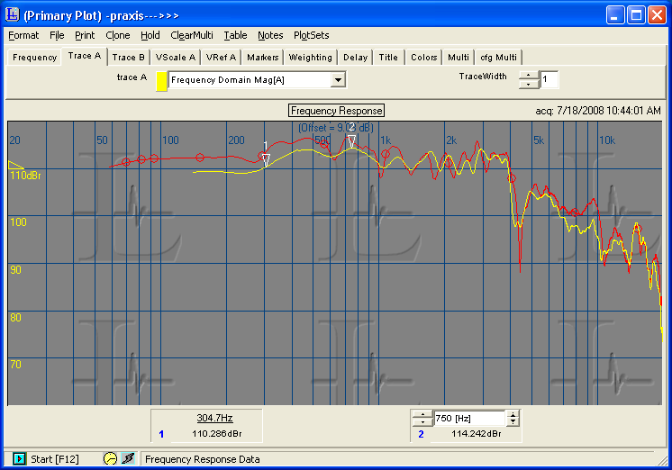
I haven't looked - plenty of work to with frequency response first. Here's some initial messing around with the woofer, going haphazardly from 1m to 10" (without changing the volume, so it's closer in as you go up). Everything below the yellow line along the bottom is invalid. The ripple in the 1m one is because the first reflection is left in. I am getting an earlier first reflection than before, and the response is tilting up as I get farther away, which wasn't happening before, so I need to do better than this, I think. Edit: poking around the web, it looks like the ~5-8dB rise in response is real... Seems like maybe I won't actually end up with anywhere near 98dB sensitivity :scratch2:.

attachment.php


I think those spikes in the nearest one are probably weirdness from being too near to the woofer, but :dunno:.

Comparison (1" TD15M measurement from AE):
TD15M-closemic.PNG


1m TD15X measurement from Brandon's drivervault page:
(google keeps thwarting my attempts to leech, but it's accessible through here: http://sites.google.com/site/drivervault/driver-measurements/15/ae-speakers-td15x/frequency-response)
 

Attachments

  • TD15M_on_axis_various_temp.gif
    TD15M_on_axis_various_temp.gif
    23.1 KB · Views: 207
Last edited:
To me it looks like you are on the right track. Just move things around to get a later first reflection, gate it out, and I think you'll be in good shape. Closer than 1 meter is too close for asessing the FR. Unless you go super close for nearfield LF. My 2 cents.
 
That looks really nice.

I will eventually have a 12" version of what you are doing, though it won't look as good.

If you want to compare notes on DE250 and QSC, I have those in use here.
 
Well, I get a blip at about 2ms no matter what I do, which I figure has to be the floor bounce. Am I supposed to be able to get useable measurements in that situation, or am I supposed to measure psuedo halfspace response by putting the speaker on the floor aiming at the ceiling?
 
I found a couple of minor issues since the first try, but now I'm just seeing a whole lot of what's below (for TD15M on-axis). Not much change moving things around, and not even much change with the speaker on the floor either (although really, the first reflection time could be similar that way, and the speaker is large enough that not much is going to be coming up from the floor).

Almost no change whatsoever from changing signal/measurement types and settings, up until the point where there obviously has to be a change. No change between HOLMimpulse and ARTA either. Of course, I'm just learning here so I could be missing all kinds of stuff on that front.

Anyway, anybody have thoughts? Does the impulse look okay? The red line is an overlay of the same measurement taken from 22" instead of 44". Impulse was a perfect match at this resolution, so I didn't overlay that.

attachment.php


One thing I don't get, and that I keep coming back to, is that both programs want me to start the gate WAAAAAY before the impulse with a second reflection this quick (to get enough samples, apparently). I think this could mean that there are very few samples in my results, leading to a smoothed result even though I have no smoothing?
 

Attachments

  • TD15M_on_axis_44inches copy.png
    TD15M_on_axis_44inches copy.png
    32 KB · Views: 188
Last edited:
One thing I don't get, and that I keep coming back to, is that both programs want me to start the gate WAAAAAY before the impulse with a second reflection this quick (to get enough samples, apparently). I think this could mean that there are very few samples in my results, leading to a smoothed result even though I have no smoothing?

You are collecting hundreds or thousands of measurements. The gating/smoothing doesn't change the raw data (at least in HolmImpulse). That's how you can change back and forth.

Is your cab directly on the floor? I measured mine from a work bench...kind of sort of midway between floor and ceiling. And I think most of mine defaulted to between 700 and 1000 Hz for gating... I would use the 1/6 octave smoothing instead of gating but I'm beginning to think that is not the way to go for modelling.

I'm still very much on the frequency response learning curve myself...

Anyone know where to find a tutorial on measuring and gating?
 
Back
Top Bottom