

You are using an out of date browser. It may not display this or other websites correctly.
You should upgrade or use an alternative browser.
You should upgrade or use an alternative browser.
dumptruck is finally building ewaves for real
- Thread starter dumptruck
- Start date


audiozaz
rtfm!? - tl;dr
You're right. I did think it could have been something like that, as the L and C values did not make sense for a straight-up textbook 1500kHz network. This seems like a very sensible approach. Seems like it's a low-Q slope with an early kneepoint that takes care of CD before the actual 2nd order function fully takes place.
az
az
Last edited:

skywave-rider
Slumming in Akihabara
So what's the next move? Are you trying other filter settings?

Russellc
Addicted Member
CD-compensation does not necessarily mean additional components. See the ewave "deluxe" design, for example. Or, check out this different view of what I did above.


Exactly. Some should probably (myself included) and reread the "PCD meddle"
over on the PE forum. This is where Zilch worked out the Deluxe version, which has no extra resistor and cap added on as compensation in the original crossover. This is not to say there is no compensation, just the particular values used, when combined with that driver/wave guide (B&C DE 250 and the QSC) have said compensation "built in".
I use the deluxe version for the high frequency filtering on my Econowave, and it works great.
Russellc
Russellc
Addicted Member
Cool, this is looking pretty good. This data will be quite valuable to me when I get around to my TD15M/BMS4550/QSC project.
Does the QSC waveguide not require any CD-compensation?
az
When using a compression driver for home hi fi use, its pretty much unavoidable. Its just the physics of a high frequency compression driver. They have a falling top end which begins too early for proper full range reproduction of the upper frequencies. Fortunately, they are way efficient compared to the typical woofer they are combined with. Reducing this efficiency and designing in the lift on the high end (which isnt really high end lift, just the other frequencies are lowered), matching the two drivers efficiency and flattening the top end response at the same time.
Russellc
skywave-rider
Slumming in Akihabara
Absolutely. It’s amazing how rich these threads are, and it’s damn tough to remember everything that went/goes on.Exactly. Some should probably (myself included) and reread the "PCD meddle"
over on the PE forum. This is where Zilch worked out the Deluxe version, which has no extra resistor and cap added on as compensation in the original crossover. This is not to say there is no compensation, just the particular values used, when combined with that driver/wave guide (B&C DE 250 and the QSC) have said compensation "built in".
I use the deluxe version for the high frequency filtering on my Econowave, and it works great.
Russellc
I was referring to the fact that a CD waveguide requires compensation to account for mass roll off compared to other types like exponential or tractrix horns. which have built in acoustical eq, (though those should only be listened to on-axis.)
How that compensation is implemented is fascinating and I usually learn something from observing dumptruck.
http://www.google.com/url?sa=t&rct=j&q=pi_speakers_info.pdf&source=web&cd=1&ved=0CFUQFjAA&url=http%3A%2F%2Fwww.pispeakers.com%2FPi_Speakers_Info.pdf&ei=YmXfT9n5LcfC6AH26Oj_Cg&usg=AFQjCNHVjK6jLzPf-533A6En4UXCZOyaiw&cad=rja
http://aaassets.peaveyelectronics.net/pdf/qwp1.pdf
Last edited:
Russellc
Addicted Member
I'm messing around with trying to get the acoustic crossover point down to 1250 (much better for the 15" driver spacing, and for the woofer performance), and it's probably not going to end up so neatly simple in this case.
If I remember correctly, Geddes uses the DE 250 @ 900....so it can be done, at least on some wave guides...fairly complex crossover too...
Russellc
Last edited:

donprice
Wound up workin' at a gas station....
My main problem with lowering the crossover point seems to be avoiding 3Ω impedance without ruining the time alignment. It is much easier to make it come together in the 1400-1600 range, seems like.
I assume the 3 ohm problem would go away if you used 8 ohm instead of 4 ohm woofers? Of course the 8 ohm crossover design would be different. I need to pick 4 or 8 ohms ASAP for the AE group buy....:scratch2:
audiozaz
rtfm!? - tl;dr
I assume the 3 ohm problem would go away if you used 8 ohm instead of 4 ohm woofers? Of course the 8 ohm crossover design would be different. I need to pick 4 or 8 ohms ASAP for the AE group buy....:scratch2:
That's right, he's got the 4ohm version... That's why I could not make sense of the part values in the LP leg of his network.
 The published impedance around 1kHz is ~12ohm for the 8ohm version, is it pretty much half for the 4ohm? It's a big plus that there's no need for a Zobel here, I like a minimal part count in a passive XO.
az
Audiozaz sent me a message including a question about the lowpass posted above having too high a Q, and I'm answering here:
First of all, you're completely right. The Q was too high. 1.25mH and 40uF works better in every way, with a tweak to the resistors on the HF to 6Ω and 10Ω. This also puts the upward null pretty much dead on the edge of the 60° waveguide pattern, which is good. A few things, though:
- This leaves the lower null at ~-15° from the waveguide, -30° being ideal. I still want to try to figure out a lower crossover point that does better there.
- It's a bit of a brain teaser measuring & designing on one axis, and then asking "now what happens when ____ is the listening axis and you move closer and farther? I have a pretty ridiculous ongoing diagram with a zillion different colored cones coming out from different spots on the speaker. I think I need to try measuring on a few different axes to get a better handle on this. Also, I'm not entirely confident in the z-offset I'm getting, and that should help.
- I need to make sure my impedance measurements are accurate at some point. In fact, I think I'm going to see if I can find bwaslo's for the CD to overlay with mine now.
First of all, you're completely right. The Q was too high. 1.25mH and 40uF works better in every way, with a tweak to the resistors on the HF to 6Ω and 10Ω. This also puts the upward null pretty much dead on the edge of the 60° waveguide pattern, which is good. A few things, though:
- This leaves the lower null at ~-15° from the waveguide, -30° being ideal. I still want to try to figure out a lower crossover point that does better there.
- It's a bit of a brain teaser measuring & designing on one axis, and then asking "now what happens when ____ is the listening axis and you move closer and farther? I have a pretty ridiculous ongoing diagram with a zillion different colored cones coming out from different spots on the speaker. I think I need to try measuring on a few different axes to get a better handle on this. Also, I'm not entirely confident in the z-offset I'm getting, and that should help.
- I need to make sure my impedance measurements are accurate at some point. In fact, I think I'm going to see if I can find bwaslo's for the CD to overlay with mine now.
audiozaz
rtfm!? - tl;dr
Thanks for clearing that out, I was having a hard time following. Assuming you designed for 5.2ohm, it gave me a Q of 1.26. Now I calculate Q being down to 0.93, so ~Chebyshev.
I'll be looking at a large inductor for my 8ohm version... Not a good time to cheap out on Xover parts when such drivers are involved though. I might go active at some point down the road though.
Lobe and null angles, is this something you calculate or measure (maybe both?)?
az
I'll be looking at a large inductor for my 8ohm version...
Not a good time to cheap out on Xover parts when such drivers are involved though. I might go active at some point down the road though.Lobe and null angles, is this something you calculate or measure (maybe both?)?
az
Last edited:
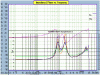
magenta: phase (ignore)I need to make sure my impedance measurements are accurate at some point. In fact, I think I'm going to see if I can find bwaslo's for the CD to overlay with mine now.
purple : bwaslo
orange: donprice
blue: me
green: zilch
sigh...
Attachments
Last edited:
I'm dragging another PM discussion into this thread. Screw it, let's make a mess! I'll go back to the beginning and put in a summary when it's done anyway.
From PM:
edit: everything below was assuming the z-offset is supposed to be positive for farther from the mic, which apparently isn't true, except it seems like it is, see later posts.
Heh, I am wondering about the exact same thing right now, big time. I am getting +11.5cm for my woofer offset when using the tweeter axis for measuring/simulating (woofer 11.5cm farther away). My woofer is deeper than the waveguide, but only a little. From what I am reading, the waveguide acoustic center is actually somewhere in the throat, but 11.5cm still looks very far.. not impossible. Now, if PCD is considering the relative z-offset as from the mic position, it is much more believable..
How Zilch got -62mm is troubling, and I'm having trouble interpreting the conversations those guys had about it. At first I thought maybe he just ended up with a polarity inverted vs. real life, so if he had clicked to reverse the polarity before finding offset, he would have gotten -8cm or something like that. BUT, if I reverse polarity, I can't get it to match up at all, whereas with polarity as I measured, everything lines up neatly at 111.5cm for the woofer.
Tonight, I'm going to try moving the measurement axis and reloading everything, and see how that changes (or doesn't change) the z-offset I end up with in PCD.
From PM:
If you can clarify me because i don't understand some things (maby my English is bad ). Zilch said (second or third page on "PCD mettle" thread) that he had some phase issues with PCD. I found that when i make Z offset 11 cm for woofer, everything lines up. You can see it here:
http://techtalk.parts-express.com/showthread.php?215536-Flex-Your-PCD-Mettle&p=1792825#post1792825
I downloaded all files Zilch uploaded and worked with them. That is the result i got. Now, earlier Zilch wrote that offset between midbass and waveguide is 63mm (tweeter behind midbass) . PCD is showing that 11cm is dead on. I'm suspecting that PCD does have some issues.
edit: everything below was assuming the z-offset is supposed to be positive for farther from the mic, which apparently isn't true, except it seems like it is, see later posts.
Heh, I am wondering about the exact same thing right now, big time. I am getting +11.5cm for my woofer offset when using the tweeter axis for measuring/simulating (woofer 11.5cm farther away). My woofer is deeper than the waveguide, but only a little. From what I am reading, the waveguide acoustic center is actually somewhere in the throat, but 11.5cm still looks very far.. not impossible. Now, if PCD is considering the relative z-offset as from the mic position, it is much more believable..
How Zilch got -62mm is troubling, and I'm having trouble interpreting the conversations those guys had about it. At first I thought maybe he just ended up with a polarity inverted vs. real life, so if he had clicked to reverse the polarity before finding offset, he would have gotten -8cm or something like that. BUT, if I reverse polarity, I can't get it to match up at all, whereas with polarity as I measured, everything lines up neatly at 111.5cm for the woofer.
Tonight, I'm going to try moving the measurement axis and reloading everything, and see how that changes (or doesn't change) the z-offset I end up with in PCD.
Last edited:
Those are being teased out of measurements taken to simulations in PCD. I will add some basic PCD instructions in this thread when I'm done, but not until I'm sure I'm doing it successfully (see above).Lobe and null angles, is this something you calculate or measure (maybe both?)?
skywave-rider
Slumming in Akihabara
...Now, if PCD is considering the relative z-offset as from the mic position, it is much more believable..
...
dumptruck, I may be totally off base because I don't know enough about PCD yet, but I was under the impression that's how it was being used. Sorry I can't offer more on that.
Re your impedance measurements -- another great scaled image -- what are you using, WT3? Would it be of any help for me to check impedance here? I have WT2, though I have not fired it up for a while.
Well, yeah I guess if you can measure a DE250 on the QSC, I can add it to those, or maybe you would be able to tell if yours matched one. I used my soundcard/preamp with a cable I made per the instruction manual for LIMP (sister program of ARTA). My plan was to buy a WT3 if I could not get my measurements done this way to match specs or other DIY measurements, and so far... I can't tell.
Russellc
Addicted Member
Those are being teased out of measurements taken to simulations in PCD. I will add some basic PCD instructions in this thread when I'm done, but not until I'm sure I'm doing it successfully (see above).
Great, I bought the mic and downloaded programs but quit when Zilch passed on. I would like to pick this back up and this sounds like a good opportunity.
Russellc