• The move to the new server is done. There are some software and database maintenance updates in process. This has us passing the hat around to help out. We appreciate any donations. Seriously, even a dollar helps. The payment page may be found here - https://www.audiokarma.org/support.html

DYI LPDA for FM

PE9ZZ

Event Horizon
Subscriber
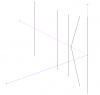
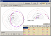
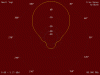
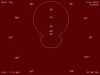
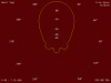
Being fed up with the crap performance of my 3 element yagi indoor FM antenna I calculated a log periodic dipole antenna (LPDA) for 86-110 MHz. The resulting array is 2 m long and has six elements (attached). The results from MMANA-GAL are pretty impressive:
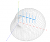
fm_6el_1.5m_lpda_3d.png

Don't you just love 3D graphics... Now there were some hurdles, like the boom that was only available in 15 mm square. Which is OK because wall thickness is 2.0 mm which should be much stronger. Too bad my order hasn't shipped yet... Also, MMANA-GAL only works with round conductors and my boom has square ones. Fortunately it is easy to recalculate using the resources I found here and here.

In the meantime I can concentrate on the 1/4 wave balun and the rotor. I believe stateside FM polarization is horizontal but sometime ago Europe changed to vertical to improve reception in motor vehicles. For my LPDA this is a problem because it must be mounted away from the mast. Also, the null at right angle of the boom is gone. Fortunately, the calculated front/back ratio is pretty good, ranging from 15 to 35 dB across the whole of the FM band.

Constructionwise it is a gamble. I want to tap M6 holes in the boom and cut M6 thread on the 6 mm elements. I hope this results in a sturdy enough antenna because I have never seen this being done. Also, attaching the coax cable to the feed point will be a challenge. I want to use thin teflon coax to make the balun and the run to the mast and have a BNC socket there. The loss will be minimal at 100 MHz. Finally, the boom needs to be attached isolated to the bracket on the rotor pole. Haven't thought out that detail. Maybe the antenna is light enough that cable ties suffice but I doubt it.

I will continue posting about my little project here. Feel welcome to chime in with ideas. Mechanical engineering is not really my forté...
 

Attachments

Register to hide this ad
You're threading elements directly into boom? Aren't some of them supposed to be insulated from boom? Heck, IDK.
 
LPDAs are not optimal for FM broadcast reception. For a given amount of forward gain and rear-lobe suppression, an optimized Yagi will be simpler, smaller, and cheaper than an optimized LPDA.

After years of modeling, the best small FM antenna I've found with decent performance is this one:

http://ham-radio.com/k6sti/five.htm

Larger antennas with more gain and much better patterns are here:

http://ham-radio.com/k6sti/metric.htm

Brian
 
You're threading elements directly into boom? Aren't some of them supposed to be insulated from boom? Heck, IDK.

No, the boom is part of the antenna. It should look a bit like this:
cae-cd-95y.jpg

This is the CD-95Y LPDA from cometantenna.com (see info sheet). Bit pricey and even more so if I want to import it into the EU. Then it gets ridiculous.

LPDAs are not optimal for FM broadcast reception. For a given amount of forward gain and rear-lobe suppression, an optimized Yagi will be simpler, smaller, and cheaper than an optimized LPDA.

This is true. However, yagis are inherently narrowband antennas. Sacrificing gain for bandwidth is always an issue. Your design looks very promising though. I'll have to find a way how to convert your parameters for MMANA-GAL. I'd love to play with it a bit. 2 m LPDA/wideband yagi shootout!

fm_6el_1.5m_lpda_10mm_stub_108.png
 

Attachments

I couldn't get the 2m yagi to work in MMANA-GAL. I guess this has something to do with the short feedline. I also didn't get my original 3 element yagi to work. This has a gamma match (and I do get performance out of it). The small yagi design with the slightly geeky swept back dipole did simulate correctly. And while doing so found some interesting features in MMANA-GAL that allows me to create more nice imagery.

First the small yagi:
small_yagi_vert_view.png

small_yagi_vert_farfield.png

small_yagi_vert_gain_fb.png

small_yagi_vert_z.png

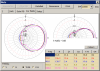
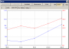
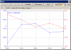
Then the results of my LPDA:
z82_farfield.png

z82_gain_fb.png

z82_z.png

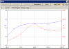
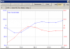
Overall the small yagi bests my LPDA in the gain department with about 1 dB. Otherwise the far field response is about the same. Flatness of the LPDA is much better and the shape of the far field response is smoother. Matching is also better.

Totally unimportant are the looks. The swept back radiator looks definitely geeky. The tapered shape of the LPDA is very pleasing to my eyes. So I will complete my LPDA, also because the metalware is expected sometime next week.

Still, it is frustrating I could not get the 2 m yagi to work. I must be doing something wrong:

2ma_108.png
 
The F/B curve for the 5-element Yagi doesn't have enough resolution for a close check, but it's not quite right. The impedance plot is way off. Check the dimensions you used.

Note that my gain figures include mismatch loss. This loss occurs when signal power is reflected at the antenna/feedline junction and is reradiated into space. For receiving antennas it's important to account for mismatch loss since it directly reduces forward gain.

I calculate F/R, not F/B. F/R is the ratio of forward power to that in the worst backlobe in the rear half-plane. It acknowledges that interference might not come from directly to the rear.

You may find this helpful:

http://ham-radio.com/k6sti/notes.htm

Brian
 
It may be how MMANA-GAL handles its model. Like I couldn't get your 2 m yagi to simulate. Real-life results invariably are different from results from simulations. I will have a challenge verifying my design once I've completed my LPDA. But I certainly will do some measurements and plot some signal levels from different frequencies. Hopefully without too much multipath.

These are three results:
small_yagi_088.png

small_yagi_098.png

small_yagi_108.png

The MMANA-GAL sim file is also attached.
 

Attachments

I can't debug your model, but the results for the 5-element Yagi are wrong. I suggest you find the cause before proceeding. Your LPDA model also may be inaccurate.

Brian
 
Could be that the cartesian conversion of the driven element is wrong. I used the length (753 mm) as Z parameter and it should be 708 mm.

Wait a minute! My sim has vertical polarization! If you look to my vertical response it is identical to your horizontal:small_088.gif

small_yagi_vert_088.png

small_098.gif

small_yagi_vert_098.png

small_108.gif

small_yagi_vert_108.png
 
Last edited:
I wasn't looking at your patterns. I was using your calculated F/B and then extracting F/B values from my patterns since I list only F/R.

Your impedances are closer now, but they are still off. Impedance is most sensitive to dimension errors, the pattern is next, and gain least sensitive.

I list numerical results every MHz from 88 to 108 MHz. Your results should be very close (when you take mismatch loss into account for gain). MMANA does not do some corrections for MININEC that my program does, but for this model the differences should not be great.

Before you commit to vertical polarization, make sure that's what the stations you want to receive use. My understanding is that polarization varies across Europe. Some people use both a horizontally polarized antenna and a vertically polarized one and switch between them.

Brian
 
In addition to mismatch loss, MMANA has two issues you should be aware of. Like any uncompensated MININEC implementation, results have a frequency offset. You'll find correct results lower in frequency than expected. The frequency offset amount depends on element diameter. The second issue is that it will report gain up to 0.5 dB too high for some models. The metric Yagis that use loop feed have this problem. The bent-DE Yagi does not.

Brian
 
Last edited:
Before you commit to vertical polarization, make sure that's what the stations you want to receive use. My understanding is that polarization varies across Europe. Some people use both a horizontally polarized antenna and a vertically polarized one and switch between them

AFAIK all of the Netherlands is vertical. As for the rest of Europe, I am not aware of any station still using horizontal polarization. For now my ambition is only local/regional use for quality reception that I now lack. Any occasional propagation catch is nice to have.

As for accuracy, a logper is tolerant for dimensional errors due to its wideband nature. I did find that my antenna is a bit on the small side when I simulate outside the band limits. Further, I never take any output of a simulator as gospel. Been burned too many times. Small differences between programs/models don't bother me and are expected (LTSpice, anyone?).

I embarked on this little project because many years ago I worked with commercial FM LPDAs and they were awesome. I therefore am biased and since I found nothing on a DIY FM LPDA decided to create one myself. We'll see how it works out. Hope to get my aluminium tubing/rods sometime next week.
 
A common LPDA trick you may want to try is to short the feeder at the longest element. As I recall, this improves the pattern.

Consider spacing chokes along the feedline in the vicinity the antenna. Otherwise, with the feedline parallel to the vertical elements you may have significant coupling. However, it mainly degrades backlobe rejection, which won't be that good to start with. See this for more about chokes (current baluns):

http://ham-radio.com/k6sti/balun.htm

The only antenna with multiple driven elements I currently recommend for FM is this one, and only when you need extremely low backlobes:

http://ham-radio.com/k6sti/ly.htm

Brian
 
Last edited:
A common LPDA trick you may want to try is to short the feeder at the longest element. As I recall, this improves the pattern.
Already done, and it did. Also included a stub which improved it even more (F/B). I can prolly go even better than what I now have but I'm satisfied with this result. And with these optimizations tolerances do get tight.
 
I forgot to mention that you can easily model the effect of the mast. Use the intended length, diameter, and protrusion into the antenna plane. Then experiment with the antenna position relative to it. You may find that antenna performance is less sensitive to the mast than you expected. That could let you use a shorter offset arm if you don't intend to rear-mount the antenna, which is best electrically.

I've modeled high-performance vertically polarized Yagis with a mast in the antenna plane. The pattern degradation was striking. However, once the mast was a foot or two behind the reflector, performance quickly returned. You'll see commercial installations of VHF Yagis with the reflector just a few inches from a tower leg. I was skeptical of this practice before I modeled such geometries, but now I think the installers knew what they were doing.

If you decide you need much better sidelobe and backlobe rejection, here is the best way I know to get it with vertical polarization:

http://ham-radio.com/k6sti/vys.htm

Brian
 
That is an excellent suggestion! My mounting bracket is only 25 cm long and it is easily included in the sim.
 
By mounting bracket I think you mean offset arm. It won't make any difference since it is orthogonal to the elements and bisects them. But the mast can have a large effect.

Brian

Edit - After thinking about it, your model will be more accurate if you include both the arm and mast. Although the arm won't couple to the elements, it will modify the mast current.

The mast model is almost always approximate since the mast often couples to conductors and structures that can't be easily modeled. But a model still can provide insight. Vary the mast length to see how much it affects things. Use a free-space model. Modeling over ground will only obscure things.

One thing I've done for vertically polarized antennas is to use a nonconductive mast in the vicinity of the antenna. It doesn't have to extend that far below the antenna elements to really help.
 
Last edited:
It actually is a bracket. Whatever the case, modeling indeed will provide some insight. In the meantime I haven't even started with the construction. To my chagrin my materials haven't even been shipped...

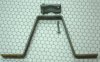
Bracket:

bracket_crop.jpg

I have to get new M10 bolts because these are too short...
 
Last edited:
Yeah! Got my aluminium hardware!

metalware.jpg

end_cap.jpg

Now I only need those bolts and then I can start building it!
 
And it is already done!

assembly_test.jpg

I did a preliminary test downstairs and it is about the same as the current antenna:

old_3el_workbench.jpg

Test downstairs (you can see the analyzer i the background):

test_downstairs.jpg

Now I only hope that when I replace the current 3 element antenna it improves significantly...
 
Back
Top Bottom