• The move to the new server is done. There are some software and database maintenance updates in process. This has us passing the hat around to help out. We appreciate any donations. Seriously, even a dollar helps. The payment page may be found here - https://www.audiokarma.org/support.html

Dynaco (kit?) ST-70 - hmm, someone's been in here before ...

Johnny_Law

o.O
Subscriber
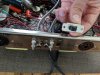
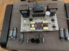
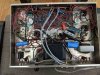
Very excited to buy this ST-70 a while ago, but it's been waiting for me to verify that everything looks good before I plug it in. From the caps up top, I could tell that someone had done some work before, but now I've opened it up and see that someone did much more work than I assumed.

I would love some help identifying all the work that's been done, and deciding what I need to do now. For example it appears that the can cap is original. The black power wires that have been added to the power input and threaded through the chassis go to external fans installed on the dust cover.

Notable observations thus far:
-Rectifier has been replaced w/ a diode, with a small flat gold cap (that I recognize but can't place) across it
-0.1uF, 0.05uF caps up top obviously have been replaced
-Mono / Stereo switch removed (and was found banging around inside)

A handwritten note came with the amp - perhaps it sheds some light on what needs to be done - since I've never plugged it in, though, I can't personally verify any of it:

-Sometimes a hum / buzz vibration in chassis when turned on until warm
-Sometimes hear a little pop, then sound gets louder, when warming up
-Raspey in right channel with fair amount of siy(?handwriting) put through
IMG_20190803_113057.jpg

IMG_20190803_113113.jpg

IMG_20190803_113212.jpg
 
Last edited:
Register to hide this ad
Can cap may be original, but it might not be in use. Looks like a lot of replacement caps under there. Same thing was done with my Magnavox 8804.

The RCA input jacks front and back.

I think you have more pots than original.

Some valve sockets replaced.

I get my ST-70 on Monday if UPS is nice and on time, but mines been modified as well.
 
Last edited:
Priority #1,... get an Owners Manual immediately.

Dynaco did a great job posting a schematic inside the manual. It is VERY clear and VERY concise.

If this were mine, I'd pull the mods out and get the unit back to stock configuration. Some of those caps look 'boutique-ish' to me so hold onto them,...you might be able to re-use/recycle them for sure.
 
With the extra two trim pots added it looks like separate biasing for each output tube was added. Hum could be coming from the added RCA jacks added at the back being so close to the AC voltage and power transformer.
 
Priority #1,... get an Owners Manual immediately.

Dynaco did a great job posting a schematic inside the manual. It is VERY clear and VERY concise.

If this were mine, I'd pull the mods out and get the unit back to stock configuration. Some of those caps look 'boutique-ish' to me so hold onto them,...you might be able to re-use/recycle them for sure.
I agree here. The original assembly manual is good and easy to follow.
 
Whatever you do, don't get frustrated. Take your time going through circuits & wire runs, compare against the schematic. Again, it's very clear and a ton 'o room to work in. There's also a voltage chart to verify work.

These amps are fantastic and have a definite following. Was in the same boat as you but decided to keep mine stock. Only changed the filter caps, selenium rectifier stage, and a resistor here & there.

In your pic, hold on to that power switch. Test it to make sure that the contacts are good. You can open it up and investigate this. Identifying those mods isn't my forte' but might be for other AK'ers here.

EDIT: Your amp has good bones and looks complete so you're in a good place with it. :thumbsup:
 
Jonny_law, what you have is an undocumented wreck.
In your place i would :
- get the dynaco manual
- remove everything below the chassies
- get a fresh cancap from dynakitparts, and a bias replacement kit
- see if the board can be rescued using original component values, if not get replacement board, made for alternative friver tube
- start rebuild as a original dynaco st70. Hopefully nothing is destroyed that cannot be found as spare
- get a matched quad EL34 and a 5AR4. Junk ( or sell) the ones that came with the amp.
- install a new 3-prong power cable, connect the green ground to an eyelet in a screw that has no other use.
 
^^^Agree with a lot of what peterh states but test those tubes, first.

They look like Gold Lions and might be still worthy.
 
One more thing of note, then I'll shut-up,...

Not sure as to why the previous owner only swapped out (2) sockets on the EL34 and the single 7199? The white ones look ceramic. Cutting corners or trying to save a few bucks? Strange.
 
Thanks everyone - @8xlaxx please don't shut up!

I do have the manual, so I suppose first step will be tracing everything to document what's been changed. This may result in stripping it down, but I'd rather know what I'm looking at before I blindly strip it down.

The Gold [edit]Aero EL34 tubes have labels on them - maybe they weren't a matched quad - three say "62" and one says "64" - not sure what it means. (The added bias pots would make sense if this were the case... I think)
 
Last edited:
You've got the major players in here for the ST-70, both 'peter's' are present and both are very helpful. Agree with above,... no power yet until some items are swapped out and checked.

You're going to be able to get it running great @Johnny_Law ! You're also on the right track with the Owners Manual. Did yours have the schematic poster inside? That foldout poster is huge and well illustrated.

Like a few others mentioning here, keep it stock.
 
Fantastic. Thanks everyone! I have the digital manual - hopefully will suffice.

Like I said, no power will run into this until I'm OK with it!

No desire to mod anything here. I was hoping it had been refreshed, and not modded. Ah well. I should have noticed the clues (new bias pots etc.).
 
Jonny_law, what you have is an undocumented wreck.
In your place i would :
- get the dynaco manual
- remove everything below the chassies
- get a fresh cancap from dynakitparts, and a bias replacement kit
- see if the board can be rescued using original component values, if not get replacement board, made for alternative friver tube
- start rebuild as a original dynaco st70. Hopefully nothing is destroyed that cannot be found as spare
- get a matched quad EL34 and a 5AR4. Junk ( or sell) the ones that came with the amp.
- install a new 3-prong power cable, connect the green ground to an eyelet in a screw that has no other use.
AGREED
 
Thank you! My first steps await. A trip to the dentist - fantastic. I've just got to think like an orthodontist!

It's so wonderful that new boards are available. I loathe lifted leads.

Woops you're right, they are Gold Aero EL34.
 
Make sure the leads of the new discrete main filter capacitors haven't been connected directly in parallel with the terminal lugs on the bottom of the can capacitor. It may seem like an easy way to install new caps, but if one or more of the sections of the old cap can decides to short internally, things may go pear-shaped fast. :eek: If this has been done, unsolder them and install terminal lug strips to re-mount the capacitor leads.
-Adam
 
Thank you! My first steps await. A trip to the dentist - fantastic. I've just got to think like an orthodontist!

It's so wonderful that new boards are available. I loathe lifted leads.

Woops you're right, they are Gold Aero EL34.
One thing is dump the board and order a VTA replacement. Otherwise rip it all out and rebuild it according to the original manual. THEN do any modifications if you choose. Don't be fooled, the basic ST-70 was a darn good amp. Get it back up to original and take it from there.
 
Here we go ... observations compared to the Dynakit manual. Starting with the power supply.

Aside from the external fan power wires, a circular dime-sized thing (metal? fuse?) in the power line after the fuse.

IMG_20190804_111406.jpg

Selenium rectifier replaced w/ a diode. Has a Siemens film cap (MKT?) across it.

IMG_20190804_112026.jpg

Bias capacitors removed, and replaced with a 150uF / 75V Sprague electrolytic and a 100uF / 100V Intercap electrolytic which is bypassed with another Siemens film cap.

IMG_20190804_113215.jpg

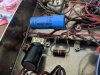
And finally ... drum roll ... the can cap. The 6.8kohm and 22kohm resistors are still there.
  • A not touched.
  • B a 22uF / 450V Samwha electrolytic bypassed w/ a .047uF / 600V orange drop wired across B
  • C a 22uF / 500V IC electrolytic cap wired across C
  • D a 30uF / 500V Sprague electrolytic wired across D
Note that the can cap was not taken out of circuit. All wiring of these caps was done across the can cap terminals. All wiring & solder was done poorly and with loose electrical tape (which since fell off) for insulation.

IMG_20190804_113258.jpg

IMG_20190804_113332.jpg
 
Last edited:
Back
Top Bottom