

You are using an out of date browser. It may not display this or other websites correctly.
You should upgrade or use an alternative browser.
You should upgrade or use an alternative browser.
Dynaco (kit?) ST-70 - hmm, someone's been in here before ...
- Thread starter Johnny_Law
- Start date


 I agree with Petercapo....strip it back to the chassis and re-build it properly.
While you're at it remove the tranny's and polish the chassis.
That's how I restored mine and I was very proud of the results. I got some chrome polish from an auto parts store and polished the chassis to a near mirror finish.
I learned a lot, took my time and enjoyed the experience.
Good luck.

Continuing the tour ... any guesses as to why any of these things were implemented in the first place? Like for example, thanks @Lavane for the tip on the thermistor. That seems like a logical mod. I'm sure at some point, the rest of this was logical to someone too?
V1 appears unmolested.
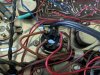
The bias pots are correctly wired to eyelets 6 and 21.

Rear RCA inputs have been installed, and are wired to the front input RCAs (grey wire in foreground as we saw before, making additional note here for science).
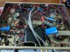
These wires are shielded - the shielding is soldered together and soldered to chassis ground, but not connected to anything else (this seems like a potential source of hum).
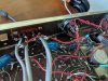
V1 appears unmolested.
The bias pots are correctly wired to eyelets 6 and 21.
Rear RCA inputs have been installed, and are wired to the front input RCAs (grey wire in foreground as we saw before, making additional note here for science).
These wires are shielded - the shielding is soldered together and soldered to chassis ground, but not connected to anything else (this seems like a potential source of hum).
The inputs are sent to individual bias pots, then from these new bias pots to eyelets 7 and 17. But one tab from each bias pot is grounded to the chassis.
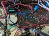
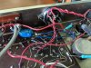
But - now this one is weird - the input ground is connected via resistor across the blue inductors (I think they're inductors? each says "18000H 35V") into the input signal wire that goes to the pots. I'm at a loss here.
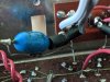
But - now this one is weird - the input ground is connected via resistor across the blue inductors (I think they're inductors? each says "18000H 35V") into the input signal wire that goes to the pots. I'm at a loss here.
The shield on those cables should only be soldered to ground at one end.
Thanks - so that seems correct at least. I'll see if I can learn why!
Moving to the PCB.
Eyelet 19 is grounded to the chassis (same ground shared by the can cap caps) across an 0.047uF orange drop.
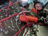
The 0.1uF 7199 - to - EL34 (name of them?) caps have been replaced with 1mF / 600V Potter caps. The two on the right are loose, looking underneath this is because of lifted leads, not broken solder joints. (Great.)
The 0.05uF caps have been replaced with 0.1uF Mallory orange caps.
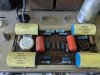
The 390pF caps have been replaced with blue 390J caps; the 82pF caps have been replaced with similar blue caps but I cannot read what value they are.
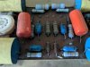
Eyelet 19 is grounded to the chassis (same ground shared by the can cap caps) across an 0.047uF orange drop.
The 0.1uF 7199 - to - EL34 (name of them?) caps have been replaced with 1mF / 600V Potter caps. The two on the right are loose, looking underneath this is because of lifted leads, not broken solder joints. (Great.)
The 0.05uF caps have been replaced with 0.1uF Mallory orange caps.
The 390pF caps have been replaced with blue 390J caps; the 82pF caps have been replaced with similar blue caps but I cannot read what value they are.
Last edited:
The output tube wiring appears mostly original, but with two modifications:
1 - some kind of capacitor (encased in heat shrink so mystery for now) going to pin 4 of each.
2 - 1k resistors from pin 5 of each EL34 socket going to the PCB instead of to the socket's pin 6. They are each wired to one side of each big yellow 1MFD cap on the PCB.

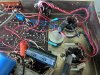
1 - some kind of capacitor (encased in heat shrink so mystery for now) going to pin 4 of each.
2 - 1k resistors from pin 5 of each EL34 socket going to the PCB instead of to the socket's pin 6. They are each wired to one side of each big yellow 1MFD cap on the PCB.
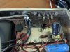
And finally, the output terminals appear original. Can't spot any deviations here. The previous owner left it with a screw in the left channel's 8 ohm terminal, and the right channel's 16 ohm terminal, who knows why?

That concludes the tour through this mysterious, dare say dangerous, ST-70.
The can cap mess is the first thing that has got to go. That's dangerous!
I am very curious about other things and want to comprehend the intention before I pull it out:
-The Siemens cap across the rectifier diode - why?
-The input line bias wiring, running the ground into the signal via a resistor - why?
-The capacitors on pin 4 of the EL34 sockets - why?
-The 1k resistors to pin 5 of the EL34 sockets ... wait, looking at the circuit diagram, this is correct (p.8 of the ST-70 manual) although the 1k resistors are shown going to pin 6 of the EL34 sockets and then to the PCB on p.18 ... I guess there's no need to run it to pin 6
-The different sized bias caps, with the Siemens bypass cap across one of them ... why?
That concludes the tour through this mysterious, dare say dangerous, ST-70.
The can cap mess is the first thing that has got to go. That's dangerous!
I am very curious about other things and want to comprehend the intention before I pull it out:
-The Siemens cap across the rectifier diode - why?
-The input line bias wiring, running the ground into the signal via a resistor - why?
-The capacitors on pin 4 of the EL34 sockets - why?
-The 1k resistors to pin 5 of the EL34 sockets ... wait, looking at the circuit diagram, this is correct (p.8 of the ST-70 manual) although the 1k resistors are shown going to pin 6 of the EL34 sockets and then to the PCB on p.18 ... I guess there's no need to run it to pin 6
-The different sized bias caps, with the Siemens bypass cap across one of them ... why?

8xlaxx
Have you ever seen a spleen that large?
Not sure how others feel about it but the board seems fairly touched up in several places. Points #15 and #22, especially. Some heat has been to this board around the 7199s but that's typical.

Where the caps have lifted you might be able to get away with a jumper wire or solder a tinned, non insulated solid jumper to the board directly, being careful of heat from your soldering station.
Otherwise, you're possibly looking at a new board purchase (?).
Where the caps have lifted you might be able to get away with a jumper wire or solder a tinned, non insulated solid jumper to the board directly, being careful of heat from your soldering station.
Otherwise, you're possibly looking at a new board purchase (?).
Not sure how others feel about it but the board seems fairly touched up in several places. Points #15 and #22, especially. Some heat has been to this board around the 7199s but that's typical.
One of the 7199 sockets was replaced - actually the other side from that pic - but all solder joints look shiny compared to others so who knows, maybe someone reflowed them. Hmm.
-The Siemens cap across the rectifier diode - why?
Figured this one out: https://audiokarma.org/forums/index.php?threads/bypass-capacitors-across-rectifier-diodes.469495/ quote copied below. This makes sense to me so I'll keep it.
Those capacitors are there to suppress diode switching noise. Too large a capacitance will start to pass AC around the diodes but the value you suggest should be OK.
As for the type of capacitor, there is no need for audiophile-grade capacitors in that application. Save the film capacitors for something else. Ceramics are just fine.
8xlaxx
Have you ever seen a spleen that large?
Do you have a DMM to buzz out the resistors? I see the white, 15.6Ohm @ 1% there and are critical to biasing the amp,...they typically will move out of tolerance.
Do you have a tube tester to check tubes?
Not seeing a ton of $$ coming out of your pockets to get it going again.
Do you have a tube tester to check tubes?
Not seeing a ton of $$ coming out of your pockets to get it going again.
Returning to @petercapo comments earlier ...
Check - coupling caps are 10x the original size! (1mF now). Can easily replace w/ 0.1uF caps.
Check - looks like the blue 390J (pF?) is indeed rated to only 630V. Will replace.
The coupling capacitors on the PCB are large. This could mean that their values have been increased, which is an idea that gained some traction over the years but might also cause the amplifier to become unstable. Their values should be checked. The original values result in a stable amplifier.
Check - coupling caps are 10x the original size! (1mF now). Can easily replace w/ 0.1uF caps.
The small capacitors (390pf and 82pf) on the PCB have been replaced, but it is a common mistake to replace the 390pf with a part rated for less than 1KV. The 390pf needs to be rated for 1000VDC. The 82pf should be fine rated at around 600VDC.
Check - looks like the blue 390J (pF?) is indeed rated to only 630V. Will replace.
Do you have a DMM to buzz out the resistors? I see the white, 15.6Ohm @ 1% there and are critical to biasing the amp,...they typically will move out of tolerance.
Do you have a tube tester to check tubes?
Not seeing a ton of $$ coming out of your pockets to get it going again.
Noted on critical nature of resistors for biasing the amp, check. I have a hunch I'll pull the added input bias circuitry anyway. (Once I figure out what the heck is going on, my curiosity as noted above.)
I do have a tube tester, but I don't have a tube tester tester, i.e., no idea if it works. Got it and have never used it!
Oh and I should mention what may be La Pièce De Résistance, the icing on the cake, in the name of convective heat transfer, the custom chop top and fan setup:
(Should I leave them? )
)

(Should I leave them?
)
It's hard to tell for sure, but some of what you see might represent an attempt at an implementation of the original Van Alstine "mod" for the Stereo 70.
Wow, you've connected the dots. I didn't mention that I found something else, but I thought it was a name tag so I peeled it off. This label was stuck onto one of the transformers:

Lavane
Lunatic Member
If it were mine I don't think I would spend the time chasing fires. The parts to restore it to it's original form wouldn't really cost a huge amount of money. Even with buying a reproduction PCB from Dynakit. The assembly manual is very good and takes you step by step. It may look difficult, but once you strip everything out starting over from the beginning it's pretty easy if you follow the instructions.
Thanks guys, I'm excited that it doesn't seem to hard to return to original!
Why should I choose the more painful path of learning about the Van Alstine mods and the intent behind them before doing so? I don't know. But I'm going to do some reading (starting here maybe) and see if I can at least learn a thing or two before HULK SMASH time.
Why should I choose the more painful path of learning about the Van Alstine mods and the intent behind them before doing so? I don't know. But I'm going to do some reading (starting here maybe) and see if I can at least learn a thing or two before HULK SMASH time.