• The move to the new server is done. There are some software and database maintenance updates in process. This has us passing the hat around to help out. We appreciate any donations. Seriously, even a dollar helps. The payment page may be found here - https://www.audiokarma.org/support.html

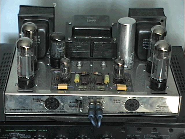
Dynaco (kit?) ST-70 - hmm, someone's been in here before ...

I get wanting RCA jacks in the rear. But then it helps to keep the signal path as short as possible to reduce noise. If you want them at the rear it may help to have just one set. Removing the ones at the front. And try routing them as.far away from any AC wiring as possible.
 
Here we go ... observations compared to the Dynakit manual. Starting with the power supply.

Aside from the external fan power wires, a circular dime-sized thing (metal? fuse?) in the power line after the fuse.

View attachment 1581412

Selenium rectifier replaced w/ a diode. Has a Siemens film cap (MKT?) across it.

View attachment 1581414

Bias capacitors removed, and replaced with a 150uF / 75V Sprague electrolytic and a 100uF / 100V Intercap electrolytic which is bypassed with another Siemens film cap.

View attachment 1581416

And finally ... drum roll ... the can cap. The 6.8kohm and 22kohm resistors are still there.
  • A not touched.
  • B a 22uF / 450V Samwha electrolytic bypassed w/ a .047uF / 600V orange drop wired across B
  • C a 22uF / 500V IC electrolytic cap wired across C
  • D a 30uF / 500V Sprague electrolytic wired across D
Note that the can cap was not taken out of circuit. All wiring of these caps was done across the can cap terminals. All wiring & solder was done poorly and with loose electrical tape (which since fell off) for insulation.

View attachment 1581457

View attachment 1581458

As I figured, the can has been (messily) left in circuit. Either replace the can with one from Dynakit Parts or somesuch, or install a terminal lug strip as I suggested earlier, and install new discrete capacitors of the correct values (the added ones do not have the correct voltage ratings to be used alone). In the latter case, it's fine to leave the unconnected can in place. Also, make sure that the first filter section (identified on the can with the 'D' shape) is no larger than 40µF if you're planning to use a tube rectifier.

As others have stated, the cap values on the board are way too large. Return the whole board to as close to the stock values as possible. If you haven't seen it already, my restoration article has some good pointers on fixing and troubleshooting these units. Good luck!
-Adam
 
^^^Very simple and detailed link @AdamAnt316. Nice work.
Glad you enjoyed it! :) I wrote it after me and a friend (hi, Ted!) each went through the process of restoring ST-70s. Also, I was dismayed by the fact that many people seemed to suggest that the stock circuit was lousy, and how many websites sold driver board upgrades. Over time, I've softened the text on that page regarding upgrades to some extent, but I still run my ST-70 with its original driver board with the stock capacitor values.
st70_3.jpg
 
"Those new to an ST-70 then owe it to themselves to first properly restore it to its original configuration, and then listen to it carefully for an extended period of time. Then, if you are looking for a different kind of sound, so be it. But at least find out what caused it to outsell everything else by such a remarkable amount to begin with!" - Dave Gillespie

^^^Final conclusion in that article.
 
Glad you enjoyed it! :) I wrote it after me and a friend (hi, Ted!) each went through the process of restoring ST-70s. Also, I was dismayed by the fact that many people seemed to suggest that the stock circuit was lousy, and how many websites sold driver board upgrades. Over time, I've softened the text on that page regarding upgrades to some extent, but I still run my ST-70 with its original driver board with the stock capacitor values.
st70_3.jpg

I too, was getting sucked into the upgrade / modification saga on the net.

I'm a firm believer in the KISS principle and went only with what you had described in the first few steps outlined in the link. :thumbsup:
 
If you haven't seen it already, my restoration article has some good pointers on fixing and troubleshooting these units. Good luck!
-Adam

Thank you Adam and YES! Your article was one of the first I found and bookmarked and is extremely helpful! I'm humbled that you're posting in my thread - thanks!

I think there is a concern that somewhere in the morass there might actually be a redeeming tweak that was done to the circuit that you don't want to lose.

Nailed it, I am worried I'll either throw away a valuable tweak that I simply don't know enough to appreciate, or, more importantly, throw away the opportunity to learn why a given tweak was made! I am an engineer and an optimizer at heart, and grew up modifying cars to make them faster, so usually my status quo is to toss the original engineering out the window under the assumption the parts & values used were because of cost control; the assumption that now, with better parts and no production budget to worry about, I can do better. BUT - I hear you (and everyone who's chimed in) loud and clear! That the original engineering is sound, and the aforementioned assumption may be rash in this case.

I think a wise move would be to return to original - or at least close enough - listen, and THEN decide if I think something is missing ...

Over time, I've softened the text on that page regarding upgrades to some extent, but I still run my ST-70 with its original driver board with the stock capacitor values.

(Your ST-70 looks beautiful by the way ... a good goal fr me!) ... Naturally I'm curious as to how the original text read. :idea:
 
@Johnny_Law

I'd be interested to know what outputs you'll be using with the ST-70? Your Snells?

@AdamAnt316

Are you still using the Beovox M70s?

So far, the apple didn't fall too far from the tree,...running A25s here. :biggrin:


(no intent to hijack thread, just inquiring)
 
@Johnny_Law

I'd be interested to know what outputs you'll be using with the ST-70? Your Snells?

Unfortunately my Snells are all gone - which pains me. I have to wait for my Snell fix until I visit my parents, my father has E/III and E/II.

I'm planning on running the ST-70 with a Dynaco PAS-3X that I recently acquired (and need to restore too, thankfully it's all original) with my revolving door of high efficiency speakers including JBL L300, Altec A7-800 (in larger DIY cabs), and Tannoy 12" reds.

You will hear from some that the original Dynacos cut corners to keep the cost down, and I am sure this is true to an extent. But, their success comes from smart engineering that nevertheless resulted in a satisfying product. At the risk of repetition, a point that I suspect is sometimes lost is that there is nothing keeping anyone from building the original Dynaco circuits with the same fresh parts quality that other present-day tube amps enjoy. As Dave Gillespie indicated, level the playing field, then decide.

:rockon: It seems to me that if I start with an ST-70 build with new components according to the original schematic, I'll be in a good spot.
 
Thank you Adam and YES! Your article was one of the first I found and bookmarked and is extremely helpful! I'm humbled that you're posting in my thread - thanks!
I'm always glad to help. :) I wrote the article before AudioKarma existed. Most of the knowledge I had had come via the rec.audio.tubes Usenet newsgroup, as well as web searches for ST-70 info. It seemed like the vast majority of opinions I read pointed towards the driver board either needing major changes or an outright replacement before giving the original circuit any sort of chance. I couldn't believe that to be absolutely true, so I restored the driver board in mine with stock value parts, put a signal through it, and liked what I heard. I then decided to put my experience to good use by writing an article which gave folks simple instructions on how to restore a ST-70 to working order without making major changes.
(Your ST-70 looks beautiful by the way ... a good goal fr me!) ... Naturally I'm curious as to how the original text read. :idea:

Yeah, it turned out rather nice. My ST-70 is from circa 1974, around which time Dynaco had switched to a chrome chassis, as well as a black tube cage bearing the Tyco-era Dynaco logo. The circuit board material had been changed from red phenolic to green fiberglass, which may or may not be noticeable from the (lousy) photos. Pretty much all I did in the way of clean-up was to carefully apply Brasso polish to the chrome chassis, being careful to avoid the lettering, as I wasn't sure if it'd be damaged by the polish. Here are a couple more lousy photos of my ST-70:
st70_1.jpg

st70_2.jpg


As for the original text, this is what it looked like in 2012, according to the WayBack Machine:

"A Note On Modification
Some people recommend changing the circuit board before doing anything else. I do not think this to be necessary nor desirable. Before doing any modifications, listen to the amplifier for a while after having replaced the parts outlined above. There is a reason they were built as they were, and can sound very nice with a stock circuit. Two other modifications suggested by some restorers are replacing of the input/output jacks with gold-plated ones, and removal of the stereo/mono switch from the circuit. I do not recommend replacing these parts, as it complicates things, and changes the general shape of the amplifier."
Are you still using the Beovox M70s?

So far, the apple didn't fall too far from the tree,...running A25s here. :biggrin:
Yes, I'm still using my Beovox M70s, which are wonderful speakers. Unfortunately, I don't get to run a signal through them very often, as I generally do my listening through either AKG K240 or Sennheiser HD650 headphones via an adapter box I built. As for Dynaco A25s, I have a pair of those as well, though at least one of them needs a replacement woofer.
-Adam
 
Last edited:
As a final note :
Tubes are expandable, like light bulbs. They are not that expensive if you buy new tubes.
Do yourself a favor, replace all to start the build with all "known good" components. But do get them from a reputable vendor that matches them correct AND that gives warranty on them. Don't go 'bay or "cheap offers" !
The above does not apply for the 7199 tubes where no no production exists. No new either replacements (6U8, 6bl8 or ecf80) they are
also old stock but so far still existing in large volumes. If a replacement board is deemed necessary then choose one that
uses 6bl8/6u8 . But usually the 7199 is in good condition.

Happy building and watch out for high voltage !
 
I usually suggest non-destructive disassembly, anyway, but do be very careful with the transformer leads. They can get crispy over the years, in which case you'd have an additional problem. If they are not crispy, then the other concerns are their remaining length and whether the insulation has been broken-through anywhere along their respective lengths, in particular where they exit the transformer end bells. There's a kind of clear heat shrink that remains flexible after shrinking, which could help with breaks along the original insulation. And, it could save trouble if it is possible to desolder the transformer leads without mangling their ends (assuming their ends are not already mangled).
Until Peterson's post shrink tube hasn't been mentioned. At the very leased you can get it at Harbor frt. in various size assortments. It's so much better than using elelectrical tape. It's neat and tidy. Just slide it over the solder joints between two joined wires and heat.
 
Back
Top Bottom