• The move to the new server is done. There are some software and database maintenance updates in process. This has us passing the hat around to help out. We appreciate any donations. Seriously, even a dollar helps. The payment page may be found here - https://www.audiokarma.org/support.html

Dynaco Mark III Restoration (2023)

Fwiw your son has a good eye, I'm liking those Blue bell caps.

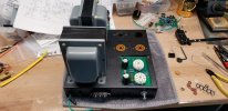
The blue bell caps have won me over with time. They have a nice pop to them. Here's a photo of a partly built unit:
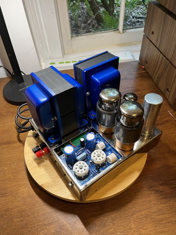

I probably should have sprayed additional layers of a clear protective coat. The Dupli-Color Blue Metalcast hasn't been very robust. It's chipped away on the top of the units just from handling it as I move it on my workbench. The side of this one didn't stand up too well against the protective cage:
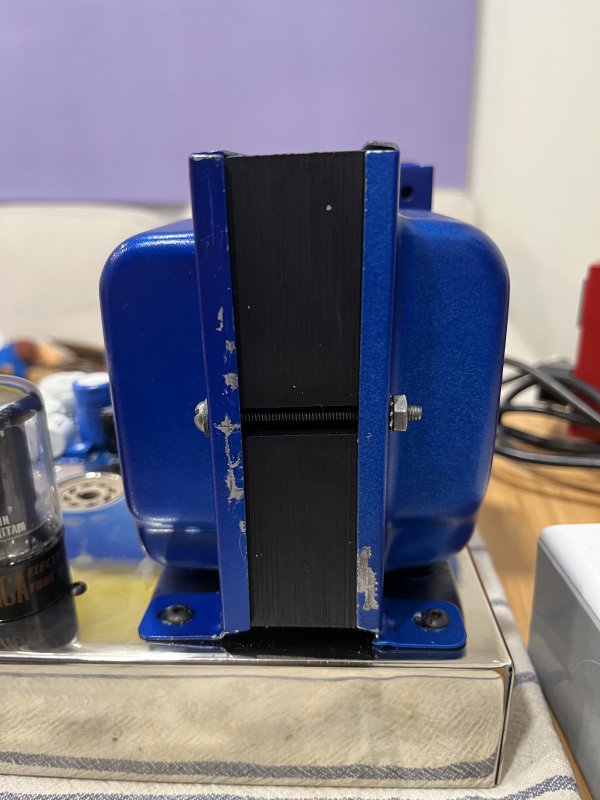

Minor aesthetic annoyances that I don't be bothered correcting at this time.
 
Bit of a bummer but I still have a few issues to work out.

When hooked up to a variac + dim bulb tester, the bulb becomes very bright when I hit 70 vac. Need to figure out where a short circuit might be.

If anyone has put together a recent tubes4hifi 6SN7 board with an SDS Labs power board (or is just far more knowledgeable than I am), feel free to offer any suggestions.

I think I have an unnecessary jumper on the PCB (between the two 6SN7 sockets), though I don't think that would be the issue.

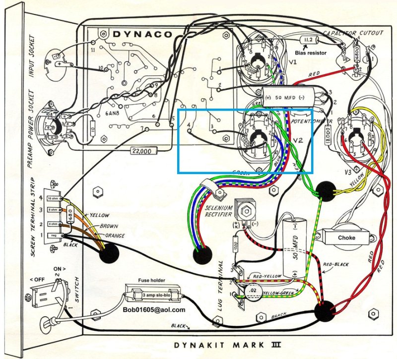
I'm also a bit unclear on v2 pin 4. The original layout had a connection between Pin #4 on the PCB and V2 Pin #4. I'm guessing the 6SN7 driver board doesn't need this connection but there's no explicit instruction on this in the notes I received from tubes4hifi. Highlighted this on this diagram:


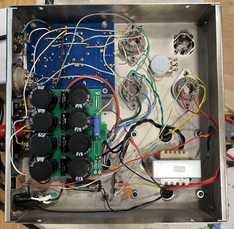
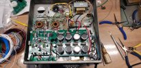
And here's a recent photo of the interior connections:

 
Last edited:
Apologies for being slow to update this thread. New baby arrived in February. She's been healthy and we've all been adjusting to the larger family.


My plan was to go with new Chinese tubes from Psvane.

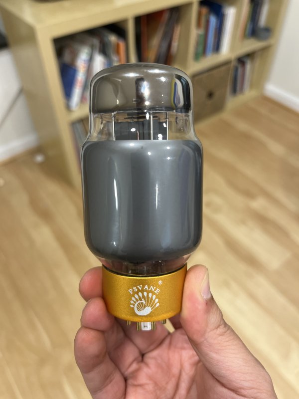
For the KT88s, I went with their newer KT88, i-T series:

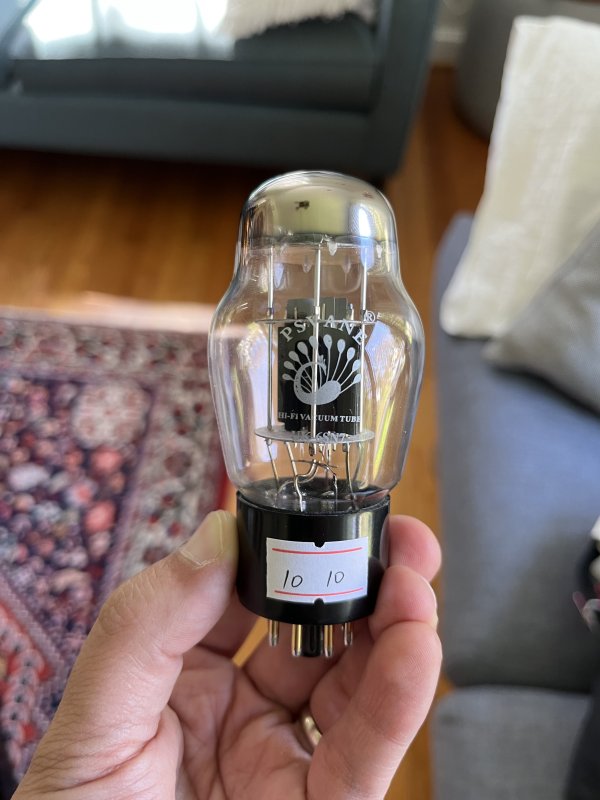
I went with the UK series 6SN7 tubes:

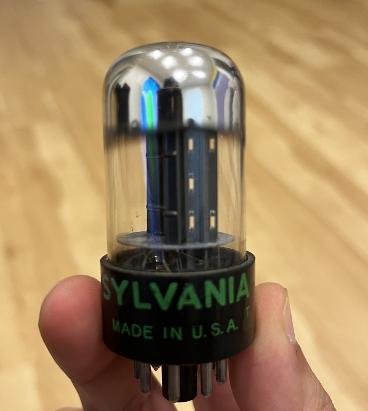
Unfortunately, it didn't occur to me to measure the spacing on the new driver board. The shouldered glass means they can't sit side-by-side on the PCB. Oops! I ultimately ended up buying a lot of well maintained Sylvania. Nothing fancy, but at least functional.


For the rectifier tube, I have some new JJ 5AR4s but will ultimately go with some RCA-branded UK-made 5AR4s (Mullards?).
Don't run those JJ 5AR4's very long. I lost two in two different amps. Both rectifiers had low hours on them. And I don't push my amps that hard.
 
Don't run those JJ 5AR4's very long. I lost two in two different amps. Both rectifiers had low hours on them. And I don't push my amps that hard.
I had a bad experience with a JJ 5AR4 as well. Mine was in a 5E3 guitar amp. Took out a 6V6 and a resistor with it.
 
Hi cosme. Any further progress made to these amps? Nice job especially the chassis.
 
That sums up where I am so far. I'll update this thread as I make more progress. However, have a baby on the way in a matter of weeks so it may get quiet for a spell between parenthood and the gradual purchase of components.

Apologies for being slow to update this thread. New baby arrived in February. She's been healthy and we've all been adjusting to the larger family.

Hi cosme. Any further progress made to these amps? Nice job especially the chassis.

Hi all. Life has been pretty busy and hectic with a toddler and now 7 month old.

This project has been on a hiatus since my last post, so not much to report on.

DBT still indicates a short circuit when I reach 70v on the variac; I still need to troubleshoot that.

I started double checking my work last night and noticed that the 5v and 6v filament windings had been reversed. Hard to blame this on the very poor state of the cloth covered wires as this was an easy test/check to do with a multimeter. That's sorted, but the short circuit continues. I'll try to find time over the next few months to work on this again. Goal is to have these fully operational by end of year.

Thank you all who cautioned here and via DMs concerning the JJ 5AR4s. And thanks to all who DM'd asking for an update or sharing your compliments. Cheers.
 
With an Amp that big I'd expect the dim bulb to glow pretty bright once the rectifier got hot. I'd put music through it and see if it comes out on the speaker terminals. If you get sound out on the dim bulb, check to make sure the correct fuse is installed and plug it into the wall...
 
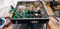
Thought I would jump in here since I'm also rebuilding/remodelling some Mk2's and using a 6SN7 board. I'm also including an auto bias board which I got paired with the driver board. First one is wired but haven't started a power yet. I want to make some resistance checks first. With the auto bias daughter board and an SDS power supply board it was a bit of a rubic's cube project. I made some adapter brackets to offset the power supply board to clear auto bias and give a bit of room for the speaker terminals and power switch. So far I think it will work out fine. I'm also trying an experiment with the rectification. I have series connected pairs of UF40007's feeding to a 6CG3 compactron 350mA damper diode to give a slow start and a little bit of voltage drop. I have it heated by the 5V winding as I've read that these things will work ok on the lower heater voltage. The old transformer leads are quite crispy so things are a little rat's nest like. I was able to move and bend them a bit by heating with a hot air gun. It's all up in the air until I start powering up to see if it all works. @cosme hope I'm not stepping on your toes by tacking onto your thread.

20230928_144219.jpg20231011_115206.jpg20231011_115216.jpg
 
Cool. I read a in a few posts the use of TV damper tubes teamed with diodes to give it a slow start up without the need of a 5AR4 tube. It also provides higher current when necessary.
 
DBT still indicates a short circuit when I reach 70v on the variac; I still need to troubleshoot that.

Hi cosme, you post raised a question for me;

Exactly what wattage is the bulb your using?
 
Initial power up. At 118VAC into the amp I'm getting 530VDC at the B+ into the output transformer. Of course the original Mk2 used a 5U4 rectifier which has much higher voltage drop. The schematic shows 465VDC B+. Makes me a bit worried if the line voltage should go up. EL34's biased at 45mA. Seems a bit on the high side. Anyone think this is a problem? Plate dissipation is just under the 25W rating of the EL34's but I rather be a bit below that. I can lower the bias to 40mA.

This is still well within the voltage ratings of an EL34 per the data sheet. The stacked caps on the SDS board are good for 630VDC.
 
I’d prolly leave it like that. What power do you get? I wanna see pics of the damper tube in all its glory lit up in the dark.
 
Haven't put any signal thru it yet. Just verifying power supply and bias setting.

I have quads of GL KT88 and TS KT220 in the wings. I'll likely go to one of these for more plate disdipation
 
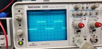
First try with signal started out looking good and then went to rubbish. I had a good clean sine and square at 1k and 10k and then the signal turned all fuzzy and unstable. A different set of tubes showed the same fuzzy unstable results so I think it's something on the board. I think it's the RCA jack. Clipped the sig gen to the wires on the back and it's ok. I also had to increase a pwr supply dropping resistor due to the higher B+. Looking good so far.

10k square wave is a bit rounded but clean. 1k looks great. These are only at 1V peak so need to install a bigger load resistor and run it up.
 

Attachments

  • 20231013_100751.jpg
    20231013_100751.jpg
    96 KB · Views: 2
  • 20231013_100804.jpg
    20231013_100804.jpg
    89.9 KB · Views: 2
I'm curious about the negative feedback. The RC pair are on the driver board as sold. At a minimum I will open it and see how much feedback is applied. At some point I will measure the frequency response and thd.
 
Due to the higher than normal B+, the voltage to the driver and PI was quite a bit high using the dropping resistor value in the documents for the new board. Upped the value from 3.9k to 10k and it's much closer. Still about 25V high at 400VDC but probably ok. Might up it to about 12k and it should be real close to target.
 
Due to the higher than normal B+, the voltage to the driver and PI was quite a bit high using the dropping resistor value in the documents for the new board. Upped the value from 3.9k to 10k and it's much closer. Still about 25V high at 400VDC but probably ok. Might up it to about 12k and it should be real close to target.
Probably more concerning with the original DC coupled concertina splitter, adjustable @ the B+ divider.
 
Back
Top Bottom