• The move to the new server is done. There are some software and database maintenance updates in process. This has us passing the hat around to help out. We appreciate any donations. Seriously, even a dollar helps. The payment page may be found here - https://www.audiokarma.org/support.html

Dynaco ST70 rebuild with Triode boards

Cabdiver

Member
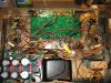
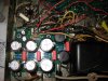
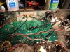
Hello everyone. I'm a newbie with more enthusiasm than good sense who bought the Triode E input (Driver) and capacitor (power) boards in an attempt to bring an ST70 back to life. I've completed the boards and placed them in position on the chassis, but have gotten stuck on the final stages of wiring them. Triode electronics hasn't returned my calls or emails, so I hope to enlist the help of others who have traveled this path before me.

I'm abandoning the power take-of sockets and using a 6922 tube in the V2 position on the driver board. Thus, per my reading, the instructions state "make your filament connections to J1 and J2..." The filament connections would be from pins 2 and 7 of the EL34 output tube sockets, but I'm unclear as to which wires would go to the J1 vs the J2. I'm assuming that left and right channel wires would be wired to the same spot.

The instructions also say to unsolder the input and output resistors, but don't indicate whether one should remove them or solder them back in position once the install is otherwise complete. And anyone know where eyelet 9 (of the input board) is?

I have a few more questions, but that's more than enough to start. I've read other forum threads which have helped tremendously, or I wouldn't have gotten this far. Thank you in advance for any help or information you can provide!
 
Register to hide this ad
It is hard to know what you are referring to with out a picture or schematic of your circuit boards.
 
My Triode Electronics manual is from about 1989 so I don't have any idea if it is the same as yours. That said, the 6.3V filament connection to the board is eyelets 24 and 25. Eyelet 9 is between eyelets 20 and 23 and connects to R107. You don't give the part number for the "input and output resistors" so I don't know which resistors you are referring to.
 
Yes that is the board I'm using. Sorry to be vague about the input and output resistors, but I'm also unclear as to which resistors the instructions refer to. (The 470k ohm resistors wired to the input jacks? The 1,000 ohm grid-stoppers? The 15.6 ohm resistors?) I just took a few pics and will try to attach them. Thank you all for your input so far.
 

Attachments

  • IMG_0339.JPG
    IMG_0339.JPG
    154.8 KB · Views: 64
  • IMG_0337.JPG
    IMG_0337.JPG
    138 KB · Views: 62
  • IMG_0338.JPG
    IMG_0338.JPG
    116.7 KB · Views: 60
So, since the filament wires aren't polarized, I can attach one from each side to J1 and the corresponding wire from L and R to J2?
 
So, since the filament wires aren't polarized, I can attach one from each side to J1 and the corresponding wire from L and R to J2?

This is just filament power, pick the side that's closest. You don't feed that from the EL34 sockets on both L and R.
 
Had to splice just a bit more wire to reach, but here it is. I'm assuming that the wires from the other channel can be removed or taped off. Should I also remove the wires from the power take off sockets to the 8 pins on the EL34s?
 

Attachments

  • IMG_0340.JPG
    IMG_0340.JPG
    121.6 KB · Views: 53
That looks correct,Maybe later get some longer wire to pretty things up a bit, The EF-86's also need those wires connected as well. The wire to pin 8 is for checking bias I believe.

Eyelet #1 to Pin 6 of V2 (EL34 tube)
Eyelet #2 to Pin 6 of V3 (EL34 tube)
Eyelet #3 to Pin 5 of left power take off socket
Eyelet #4 & #5 to Pins 1 & 2 of the left power take-off socket (Note 1)
Eyelet #6 to center lug of left bias pot
Eyelet #7 to left channel input jack
Eyelet #8 10 ohm ground isolation resistor to pin 3 of left power take off socket.
Eyelet #9 to chassis ground lug near quad cap.
Eyelet #10 10 ohm ground isolation resistor to pin 3 of right power take off socket.
Eyelet #11 to Pin 4 of V3 (EL34 tube)
Eyelet #12 to left channel 16 ohm tap on speaker output terminal
Eyelet #13 to right channel 16 ohm tap on speaker output terminal
Eyelet #14 to Pin 4 of V6 (EL34 tube)
Eyelet #15 & #16 to Pins 1 & 2 of the right power take-off socket (Note 1)
Eyelet #17 to right channel input jack
Eyelet #18 to Pin 5 of right power take off socket
Eyelet #19 to Lug #3 on Quad cap (305 volt source) (Note 2)
Eyelet #20 to Lug #4 on Quad cap (375 volt source) (Note 2)
Eyelet #21 to center lug of right bias pot
Eyelet #22 to Pin 6 of V7 (EL34 tube)
Eyelet #23 to Pin 6 of V6 (EL34 tube)
Eyelet #24 & #25 to Pins 1 & 2 of the left power take-off socket (Note 1)
Eyelet #26 & #27 to Ground connection on input jacks
 
Last edited:
True - she isn't winning any beauty contests at this point. Do I need to utilize the power take-off sockets, or do I connect the EF86's another way? Should I just leave the wires from the take-offs to pin 8 (on either side) in place? Thanks again - I appreciate your patience with a novice. [Should I post my system components as you have done?]
 
The pin 8 to socket stuff, as mentioned earlier, is your bias test point as wired normally on ST-70. Personally, I would leave that so checking/setting bias is still somewhat convenient.
 
You can run wires from your connection points already made, make sure they are twisted and away from the surface of the board to avoid hum, or you could go to the EL34's like the first one
 
So, I should leave the wire from the Take-off socket to pin 8 of the EL34's, but otherwise run wire to eyelets 4&5 (left) and 15&16 (right - to supple the EF86's) from either the EL34 (pins 2&7 from either side, I assume) or from other connection points (which ones?) I wish the Triode instructions were more clear, but, again, I really appreciate your help.
 
I've been going over those instructions and trying to understand this better. It seems from your kind suggestions I have options re: the EF86 att's (eyelets 4,5 and 15,16.) I'm not opposed to using the front sockets, though at this point their only wired to pin 8 of the EL 34s on either side. I had thought it was cleaner to not involve the front sockets, but you guys understand this stuff at a deeper level than I do. By far. It seems I should solder the 470k ohm resistors back onto the input jacks (which I've replaced.) I'll leave the other resistors in place, though the 10 ohm resistors from the front jacks to the original input board never existed on the amp, as I bought it, and I can't think of what value they would add at this point anyway. Thank you again! I'm beginning to think this puppy may actually work at some point.
 
Back
Top Bottom