• The move to the new server is done. There are some software and database maintenance updates in process. This has us passing the hat around to help out. We appreciate any donations. Seriously, even a dollar helps. The payment page may be found here - https://www.audiokarma.org/support.html

Dynaco ST70 rebuild with Triode boards

Re: rewiring, I've tried to stay with original wire, but when need be I've used 20 gauge unstranded copper, though with slightly thinner insulation than the original stuff. I also notice varying wire diameters in the new Triode instructions. Am I over-thinking this? Thanks again.
 
A little, the filament wires between the output tubes are the only wires that carry any current, the rest don't really matter for thickness
 
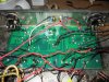
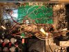
I've placed the 470k ohm resistors back at the input jacks and have supplied power to the EF86 filaments (pins 4,5 and 15,16) from the 2 and 7 pins of the EL34's. I've also tidied things up a bit, though I didn't go overboard. I'll attach a couple of pics. OK so far? Thank you!IMG_0341.JPG IMG_0342.JPG
 
If using a 6922 a wiring change is necessary per the note below:

NOTE 1: snip
The phase inverter position (V2) now has
extra flexibility to use tubes with different pinouts, to use 12AU7, 12BH7, ECC99 solder a wire from
J1 to J2 and make your filament connections to eyelets 24 & 25, to use 6CG7, 6922, 7308, or 6DJ8
do not jumper J1 and J2 and instead make your filament connections to J1 and J2 and ignore
eyelets 24 and 25.
 
I believe I've made the filament connections (from pins 2&7 of the nearest EL34) to J1 and J2 (w/out jumping them together) in no particular order as there aren't polarized. I then ran wires from the EL34 filament pins to the EF86's (pins 4,5 and 15.16.) I'm doing my best to ignore eyelets 24 and 25. Thank you for your continued interest!
 
I couldn't read the eyelet numbers in the pictures,and I didn't remember that you used J1 and J2 earlier.I was going by the instructions, I guess you are all set then.
Do you have a DBT or variac, yet to fire it up? (Dim Bulb Tester)
 
No - I've been wondering about that. Guess I should build a DBT, though at times I feel that I am one myself.
 
:rflmao:

If this is your only use for one, find a cheap lamp, and a cheap dollar store extension cord, cut one wire in the lamps cord, cut the plug off the extension cord, wire the extension cord ends to the cut wires in the lamp cord, and you are done. To test: With nothing plugged into the extension cord the light will not light, with a load like a coffee pot, toaster, etc.. the light will light with the lamp and appliance on
 
What a great idea. I watched a couple of youtubes and was planning a trip to home depot for parts. This seems quicker. I'll assume I should cut the neutral wire to/from the lamp so as to have the bulb in series limiting the current floe to the ext cord receptacle.
 
It doesn't have to be pretty, just safe and work. I built mine out of what I had laying around the shop.
 

Attachments

  • 20171107_131853.jpg
    20171107_131853.jpg
    60.3 KB · Views: 26
With only the rectifier tube installed, I plugged the amp into the tester with a 40 w bulb, then a 60. Bulb glowed brightly, then faded, then brightly for a second or so, then dimmed again, but not completely out. I've got it cruising now on that dim status, which I'm thinking is all good. (No magic smoke - at least not yet.) Am I ready to plug it into 110v, or should I find a higher watt bulb to nudge it more incrementally? Thanks again!
 
It sounds good to me! You should set the bias pots per the instructions, you may also want to check bias voltage before going full voltage and installing the other tubes
 
Now on full power and with only the rectifier tube in place, I tested the voltages of the EF86 sockets on the driver board per Triode's instructions. Pin 1 should have 55-80v; I got 367 on each side, grounding to the chassis. pins 2,7,8 and 9 should read 0 and do. Pin 3 should be between 1.2 and 1.4 v - I got 0.92 on each side. Pin 6 should be 80-110v; I got 412 on each side. Measuring voltage "across" the filaments (pins 4&5) I get 3.6v on each with black probe grounded, and 7.17v with one probe in 4 and the other in 5 ("across?") Does this pattern suggest anything to you? Does it make any sense to install the rest of the tubes and continue testing, or should I hunt for a non-fatal, but wound-incurring flaw? Nice, easy question, huh? Thanks!!

 
The front end tubes need to be installed for those measurements, if the bias is ok then it's time for the output tubes. The filament needs to be measured in AC volts. Filaments to ground would likely measure 1/2 of the value as across the connection points between the wire pairs.
connect a load across the speaker terminals, a cheap pair of speakers would be fine.
 
Last edited:
I have some older speakers hooked up. With the neg probe grounded on the chassis and the pos probe on pin 8 of the (empty) EL34 socket, I got essentially 0 volts. Would I need a tube in the EL34 socket to read the bias, or am I missing something? Do the EF86's play a role here, or the 6922 in the V2 spot? I'm game to pop them in and try the bias check again...
 
Yes, as the Output Tubes complete the circuit so the bias can be set! May need the preamp & driver tubes also for best results.

Hope it works!
 
Before you install the output tubes, measure the bias supply, it should be - voltage I don't have the schematic in front of me, Im at work. Pin 5 & 6 is supposed to be -32v on each EL-34 to start
The voltage chart is in the original st 70 build manual
 
Last edited:
Back
Top Bottom