

You are using an out of date browser. It may not display this or other websites correctly.
You should upgrade or use an alternative browser.
You should upgrade or use an alternative browser.
Dynaco ST70 rebuild with Triode boards
- Thread starter Cabdiver
- Start date
-
- Tags
- driver board dynaco st70

Cabdiver
Member
I put 2 EL34s on the left side and adjusted bias to 1.56v, per the old Dynaco instr. At first the V2 (front) tube glowed a bit more than the V3. I shut the amp off, jiggled the V3 tube and turned it back on. This time the V3 went berserk, glowing very brightly, so I shut it down again. I rechecked the wiring and confirmed that the grid resistors are all reading over 1000 ohm, then fired it up again. My thinking was that I'd check the voltage at pin 5 quickly, before the V3 tube took off again. All good - the voltage reading at pin 5 is -31.8v on both V2 and V3. The bias was off, so I readjusted it to 1.56. Both tubes glowed subtly and equally as if nothing untoward had ever happened. I turned it off again, as I'm out of time for now, but will put tubes on the right side and repeat the process. If all's well, I suppose the next step is to go through the Triode instructions and check the voltages for all the tube pins. Again, thanks for your continued help - this ON1 (Obtuse Newbie of the first order) really appreciates it!

s-petersen
Scott
Something sounds a little strange, are your tube sockets loose? They may need retensioning.
When you say glow, do you mean the filament, screen, or plate? The filament is the very center, The screen is the area around the filament, if glowing it will show mainly reflecting off the mica supports, and the plate is the outside metal wrapper that you see through the glass
When you say glow, do you mean the filament, screen, or plate? The filament is the very center, The screen is the area around the filament, if glowing it will show mainly reflecting off the mica supports, and the plate is the outside metal wrapper that you see through the glass
Last edited:

crispycircuit
Super Member
Try setting the bias to 1.25V. Maybe the tubes can't handle high current. Are these old tubes or newer stuff? I'd try setting to 1V and see how they sound.....worth a try....
Cabdiver
Member
It was probably the plate that was glowing. I'd turned the amp on and left it a moment to warm up, then smelled something. When I glanced at the amp, the V3 tube was glowing diffusely orange, not just a filament wire. As I look back, I believe I had one tube go bad in this socket previously when I was running this with the original boards, etc. still in place. (The amp had acutely developed a loud hum and I noticed the tube had brownish discoloration when I pulled it out. This and a blown fuse on another occasion prompted me to start this rebuild.) I tested with just two EL34s because I was leery of putting in my fresh, matched set of four at this point. I'll research retensioning sockets and will also clean and inspect them. Thanks again for the great suggestions.
Cabdiver
Member
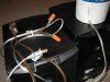
Well, I cleaned and retensioned the sockets, and removed excess solder from one of the V3 grid resistor connections, then turned it on again. This time I of course watched carefully. The V3 ran away (correct term?) again, and it appeared that the filament wires got too hot first - the generalized glow would probably have come later, but I shut it down quickly. I could retry with a different tube, or should I ponder replacing the socket? I'll take a pic of the socket connections - the miscreant socket is on the left. (I'll also post a pic of the dim bulb tester I built per a previous suggestion.)
Attachments
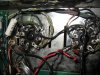
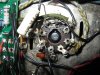

Do you know that the tubes you're trying are good? If they are not known to be good, then all this is guesswork.
Connection to pin 6 doesn't look terribly well soldered to me. Also looks like the lead on the 1K may be cut? Or is that just a solder blob?
What sort of voltage are you reading at pin 6, and does the bias pot change it ? You can test this with no tubes at all installed.
Connection to pin 6 doesn't look terribly well soldered to me. Also looks like the lead on the 1K may be cut? Or is that just a solder blob?
What sort of voltage are you reading at pin 6, and does the bias pot change it ? You can test this with no tubes at all installed.
Cabdiver
Member
I swapped tubes and got the same results, though I must point I've been mislabeling the sockets. The V3 socket (closer to the front) seems fine - it's the V2 that's been trouble (but you probably knew that.) I put the two EL34 tubes in the right side and turned it on. The readings at pin 6 of the R side are both at -34.3v; on the L side it's -36.7v at V2 and V3. The readings between pins 2 and 7 are 6.7 v (AC) in V6 and V7; 7.1 v in V2 and V3. I haven't tried turning down the bias yet - may want to find some cheaper load speakers before risking fireworks coming from the V2. I did resolder the connections at pin 6 and tested R across pins (post connection) and got ~1,100 ohms. Great suggestion, and I also remelted the solder at the driver board connections for the 6 pin. Thanks!
Cabdiver
Member
Hello again. I took the plunge and installed all 4 EL34 tubes. None of the tubes glowed too brightly and I heard no worrisome pops coming from the speakers. However, I couldn't get anything near an appropriate bias reading on the left (troublesome) side. I got readings in the 20v (not 2.0) range, while I set the right side bias to 1.25v. I tried setting the left bias lower but got higher numbers. I get -34v at pin 6 all around and 6.4v (AC) across pins 2 and 7 on all four EL34 sockets. So, before I had reasonable bias voltages but the V2 tube glowing to an extreme degree; now with four tubes in, they all look fine, but I get stupid numbers on the left bias. I hope this makes sense to someone, since I'm baffled. Thank you for your interest and help!
s-petersen
Scott
Yo may have blown the bias sense resistor for that pair (15.6 ohm) you may want to recheck it.
Cabdiver
Member
You guys are good. The right channel resistor reads 15.8 ohms; I get no reading on the left one. I also discovered that the ground wire from the left channel output ground (at the speaker connect posts) had become disconnected from the chassis ground point - maybe why the resistor failed? I guess I'll now find out how hard it is to find 15.6 ohm resistors... Thanks again!

nj pheonix
Lunatic Member
It's an oddball by itself.
Dynakits sells them
Dynakits sells them
nj pheonix
Lunatic Member
Or you can make it up from 2 resistors in parallel
Cabdiver
Member
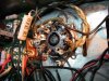
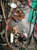
In researching this, I see that the 15.6 ohm bias (or common cathode) resistor is connected in various ways. In mine, the resistor is soldered to either pin 1 or 8 on one side, which I suppose is the same thing as those are connected anyway, and to ground on the other. I'll attach a photo or two. I'm thinking this is fine, but thought it best to give you a visual. (I've emailed Dynakits re: a replacement or combo that'll work.) Thanks!
Attachments
crispycircuit
Super Member
If the 15 ohm resistor was blown, NO current would flow and no sound would be made. The current flows to ground thru the resistor, check the grounding wiring....
Cabdiver
Member
The 15.6 ohm resistor arrived today. With it installed, get get decent readings across the output tubes (none of which glowed too brightly or crackled):
6.8 v AC across pins 2 and 7, 439-442 v at pin 3, 443-445 v at pin 4, -32.5v to -33.8 v at pin 5 and -33.1 to -33.8 at pin 6. I adjusted the bias to 1.50 both sides. I'm eager to run sound through this, but I pulled all the tubes but the 5AR4 to test the EF86 sockets on the driver board. Here the numbers don't seem to come in range: 367v at pin 1 (both sides, 55-80 expected per Triode instrs) 0.916v at pin 3 (1.2-1.4 expected) and 416 (left) 412 (Right) at pin 6 (80-110 expected.) I get 0 v at pins 2,7,8 and 9 as expected. Since I have good numbers at the output tubes is it OK to hook this up and try to make some music happen, or do I have a significant problem with the EF86 readings? Thank you again - I appreciate you getting me this far!
6.8 v AC across pins 2 and 7, 439-442 v at pin 3, 443-445 v at pin 4, -32.5v to -33.8 v at pin 5 and -33.1 to -33.8 at pin 6. I adjusted the bias to 1.50 both sides. I'm eager to run sound through this, but I pulled all the tubes but the 5AR4 to test the EF86 sockets on the driver board. Here the numbers don't seem to come in range: 367v at pin 1 (both sides, 55-80 expected per Triode instrs) 0.916v at pin 3 (1.2-1.4 expected) and 416 (left) 412 (Right) at pin 6 (80-110 expected.) I get 0 v at pins 2,7,8 and 9 as expected. Since I have good numbers at the output tubes is it OK to hook this up and try to make some music happen, or do I have a significant problem with the EF86 readings? Thank you again - I appreciate you getting me this far!