• The move to the new server is done. There are some software and database maintenance updates in process. This has us passing the hat around to help out. We appreciate any donations. Seriously, even a dollar helps. The payment page may be found here - https://www.audiokarma.org/support.html

Dynaco Stereo 35 replacement output transformers

class C exists but I don't think that really ever gets used for audio. Way too much distortion, though it seems to work OK for radio transmitters.
Class C is a single ended topology in which the output tube conducts for substantially less than 50% of the cycle. The LC tank circuit at the output of the tube "rings" at the RF frequency of operation, creating a sine wave. Efficiency is primarily determined by the length of time the tube conducts and the Q of the tank. The latter also affects signal purity (harmonic content). The RF wave can be modulated by an audio signal, but this topology is otherwise unsuited to baseband audio use.

Jack
 
Class C only works because there's a resonant circuit to turn the current pulses into a sine wave (think of pushing a swing - motion is sinosoidal, even though you only push for a small part of the cycle)
 
Class AB works due to distortion cancellation - as one tube's output is compressed, approaching cutoff, the opposite one is expanded - look at the curves - the curves spread - the transconductance increases - as current increases. Typically, class AB has distortion minimal at low power, increasing with power, then decreasing to a null at a higher power level. I wonder why people make single-ended amps with tubes designed for this (complementary) non-linear characteristic.
 
as one tube's output is compressed, approaching cutoff, the opposite one is expanded
This behavior isn't evident to me, looking at the curves. Starting at the bias position, the spacing of curves leading down toward cutoff is much more radical than the portion leading up toward increased conduction.
I wonder why people make single-ended amps with tubes designed for this (complementary) non-linear characteristic.
Can you expand on this a little? Maybe a few examples of tube types that are designed for this VS a few that aren't? I haven't heard this before.

Jack
 
Yes curves compress toward cutoff, spread before saturating (on tubes designed for class AB). Creates 2nd harmonic distortion in class A, cancels in push-pull A or AB. Even class A can deliver more than twice the SE power at the same distortion level. Look at the pentode curves for 6550 or KT-88 and you won't think about SE class A.
 
How does this cancellation work? The current is in the same direction in both halves, as opposed to the B+ ripple cancellation we know exists. With the signal power in phase and the distortion signal in phase, how does anything cancel?
The ripple waveform increases and decreases simultaneously at both ends of the transformer. Tom is talking about a signal that's moving positive at one end and negative at the other because the tubes are driven in push-pull.
 
The Mullard EL84. The closest chart has g2=300 but since we're UL it has to be interpolated with the curves raised up the chart to get near to 13.v @ 30mA. It's not "exact" but it shows how close to cutoff 13.5v is in the ST-35.
Seems to me the triode charts are better for analyzing UL static operating points. The anode and screen idle at almost the same voltage. Unfortunately, the Mullard chart for triode mode stops at 300V. In any event, I think there might be more distance to cutoff than is apparent due to the dynamic increase in screen voltage that takes place as the signal moves negative.
 
Additive is additive. It's the current that creates the flux. The signal creates the current, music or distortion. Why don't the music primary signals cancel?
It's the differential between the two ends that creates additive flux in the core. If the two ends move positive and negative simultaneously (in phase), the flux created by each half of the winding cancels. This is why a phase inverter is required.
 
I sure wish we had a Mr Whoopee 3d blackboard on this subject. I understood steam engines in the first grade.
 
But you can clearly see the predicted break in the load line where the system would transition from class A to class B.

I suspect that would show up as a narrower class A region.

I have always been told that most class AB amplifiers operate as class A up to a certain ouput power point and then class AB after that point. Is that really true? If so, at what point does an unmodified ST-35 make that change? I don't know how to read the graphs.
 
Class C is a single ended topology in which the output tube conducts for substantially less than 50% of the cycle. The LC tank circuit at the output of the tube "rings" at the RF frequency of operation, creating a sine wave. Efficiency is primarily determined by the length of time the tube conducts and the Q of the tank. The latter also affects signal purity (harmonic content). The RF wave can be modulated by an audio signal, but this topology is otherwise unsuited to baseband audio use.

Jack

exactly

harmonic content not a massive probl

**edit** stupid phone

anyway, massive harmonic content not such a big deal in a transmitter since anything outside of the desirable band is easily filtered.
 
Last edited:
I have always been told that most class AB amplifiers operate as class A up to a certain ouput power point and then class AB after that point. Is that really true? If so, at what point does an unmodified ST-35 make that change? I don't know how to read the graphs.


Pretty much. Up to a point, both tubes are conducting 100% of the output so in that respect its working like a class A amp. Beyond that point it conducts for less than 100% but more than 50% so AB.

anyway, on this graph

https://audiokarma.org/forums/index...line-calculator-6bq5-ul-st35-14w-pdf.2863957/

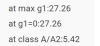
it actually says on the graph. 27.26 watts plate to plate is max output power, up to 5.42 watts is in the class A region.

upload_2023-4-19_18-1-32.png

I know at one point I knew how to calculate this manually but I'm drawing a blank on it.
 
In class A push-pull, ideally the sum of the currents in each tube remain the same, and as the "top" tube conducts more, the "bottom" one conducts less by the same amount. If both were completely linear, this would be the case. Transconductance (output current vs. input voltage) is not constant over the signal swing. (you see this as unequal spacing of plate curves) This creates 2nd order distortion... but in push pull, it cancels - as one tube decreases in transconductance, the other increases, so the sum is closer to the input signal than either alone .

6CW5 may be an extreme example: 5.6W @ 10% distortion in SE, 25W @ 1% in push-pull AB. I suspect that's a narrow optimum; and changing the load or operating point would make it worse
https://pdf1.alldatasheet.com/datasheet-pdf/view/241842/GEC/6CW5.html
 
Last edited:
Strictly speaking, a class A amplifier is in continuous conduction at full power; and a class AB amplifier is in cutoff for part of each cycle (less than 180 degrees); class B is cut off for 180 degrees, class C for more than 180 degrees (all at full output). So strictly speaking, a class AB amp never operates in class A, though it's in continuous conduction at some point below full power.
 
So strictly speaking, a class AB amp never operates in class A, though it's in continuous conduction at some point below full power.
Many years ago, the classic definition of a Class A1 power amplifier - namely that the tube never enters cutoff - generally included the statement (or at least an assumption) that it would be biased in the center of the current swing. There would be little reason to do otherwise, because that's the operating point that permits maximum symmetrical swing and output power. Referring to the small signal characteristics of an AB1 amplifier as Class A is incorrect, not only because the intended use is to be excited with a signal that pushes the tubes into cutoff, but also because even small signal operation does not occur in the most linear area of the curves. It is never truly Class A.

Jack
 
I knew this would get into a terminology discussion.

Yes AB amps are always AB amps, but there is a "class A region" where the tube conducts for 100% of the cycle up to an output level. Note the RDH doesn't have anything to say about linearity or bias points when defining Class A, only that it conducts all the time.

upload_2023-4-20_8-6-28.png


you can run a single ended tube, which by neccesity has to be a class A design, and bias it such that it makes considerably less power than it is capable of just by choosing a bad bias point. Its still class A though.
 
there is a "class A region"
There's no such thing. Class designations apply to amplifier types, not to selected areas of a waveform. The RDH definition is incomplete.

From the Radio Handbook (Editors and Engineers, Ltd.), 1947:

Class-A.jpg

Jack
 
note "normally". There is no strict requirement that an amplifier be properly biased. An improperly biased class A amplifier is still a class A amplifier, its just one that doesn't work as well as it should. Under-bias it and you simply limit maximum output swing before it starts clipping one side of the waveform.

and this doesn't also say there is no such thing as a class A region. It says that it conducts for 360 degrees. At low levels, an AB amplifier does this, therefore it fits the description of class A operation. Not full time, and not at all power levels, but there is a range of output where it does. I'm sure the cut-off bit there continues along the lines of "but less than all of the input wave cycle". If the output level is not such that it conducts less than 360 degrees then its not working in AB mode per that definition.
 
Back
Top Bottom