klamsoss
Be willing to fail and try again.
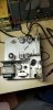
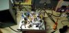
I'm still new-ish to working on gear and learn more with each piece that I work on. As such, I've picked up pieces of classic-era test gear with the intent of gaining knowledge through restoration. I paid $20 at an estate for a box full of an Eico 377 Audio Gen, a model 232 VTVM, and a model 368 sweep generator. I'm starting with the 377 because it is about half the size of my heathkit IG-82 generator, and bench space is at a premium.
The 377 had visibly leaking caps so I set about replacing the electrolytics. 20uF and 8uF caps were replaced with 22uF and 8.2uF respectively. While in there, I reflowed a few shoddy looking solder joints, checked the 3w light bulb to make sure it was good, and hit the pots and contacts with deoxit.
The tubes all tested well on my Sencore Mighty Mite, so I moved on to calibrating the instrument using the A-C Voltmeter method outlined in the user manual. This involves placing a 1000 ohm resistor across the output of the fully warmed up Generator, band switch set to "B", frequency to 200 c.p.s, and amplitude to maximum. Then, adjust the R9 pot until an A-C voltmeter across the 1000 ohm resistor reads between 10 and 11 volts RMS.
I couldn't get a reading higher than about 1.6 volts. I measured with both a Fluke 87 V True RMS DMM, and my heathkit IM-11 VTVM.
I went back and checked circuit voltages against those indicated in the construction manual. The 6SJ7 seemed to be yielding some unstable voltages despite it testing okay, so I replaced it with a known good 6SJ7GT. At that time, I also replaced the large wax 0.5uF (20%) capacitor with a 0.47uF poly from my supply. I don't have appropriate value 400V+ rated caps on hand to replace the 0.25uF wax caps.
After these updates, all voltages throughout the instrument then measured within 15% or so of those specified in the assembly manual, with exceptions:
A) Pin 1 on V-3 (the 6SN7) measured -25.5V rather than -10V. Though, oddly, I could get the voltage to increase to around -12 V by selecting band D (highest frequency band). (the V-3 measurements are all indicated as being with the generator set to square wave)
B) The manual indicates 15-20 VAC, 1000c.p.s. from the sine/square switch to ground, and I measure in the mid-low 40 volts range, and 193Hz (again, 200hZ is indicated by the instrument). The voltage here varies by only about 1.5 VAC as I rotate the indicator knob through the entire range.
Can anyone weigh in on why the output is so low? And/or why I seem to have excessively high AC voltage between the oscillator output itself and excessively low voltage within the square wave circuitry? (I suspect these are all linked).
Many thanks to anyone who can weigh in!
The 377 had visibly leaking caps so I set about replacing the electrolytics. 20uF and 8uF caps were replaced with 22uF and 8.2uF respectively. While in there, I reflowed a few shoddy looking solder joints, checked the 3w light bulb to make sure it was good, and hit the pots and contacts with deoxit.
The tubes all tested well on my Sencore Mighty Mite, so I moved on to calibrating the instrument using the A-C Voltmeter method outlined in the user manual. This involves placing a 1000 ohm resistor across the output of the fully warmed up Generator, band switch set to "B", frequency to 200 c.p.s, and amplitude to maximum. Then, adjust the R9 pot until an A-C voltmeter across the 1000 ohm resistor reads between 10 and 11 volts RMS.
I couldn't get a reading higher than about 1.6 volts. I measured with both a Fluke 87 V True RMS DMM, and my heathkit IM-11 VTVM.
I went back and checked circuit voltages against those indicated in the construction manual. The 6SJ7 seemed to be yielding some unstable voltages despite it testing okay, so I replaced it with a known good 6SJ7GT. At that time, I also replaced the large wax 0.5uF (20%) capacitor with a 0.47uF poly from my supply. I don't have appropriate value 400V+ rated caps on hand to replace the 0.25uF wax caps.
After these updates, all voltages throughout the instrument then measured within 15% or so of those specified in the assembly manual, with exceptions:
A) Pin 1 on V-3 (the 6SN7) measured -25.5V rather than -10V. Though, oddly, I could get the voltage to increase to around -12 V by selecting band D (highest frequency band). (the V-3 measurements are all indicated as being with the generator set to square wave)
B) The manual indicates 15-20 VAC, 1000c.p.s. from the sine/square switch to ground, and I measure in the mid-low 40 volts range, and 193Hz (again, 200hZ is indicated by the instrument). The voltage here varies by only about 1.5 VAC as I rotate the indicator knob through the entire range.
Can anyone weigh in on why the output is so low? And/or why I seem to have excessively high AC voltage between the oscillator output itself and excessively low voltage within the square wave circuitry? (I suspect these are all linked).
Many thanks to anyone who can weigh in!