• The move to the new server is done. There are some software and database maintenance updates in process. This has us passing the hat around to help out. We appreciate any donations. Seriously, even a dollar helps. The payment page may be found here - https://www.audiokarma.org/support.html

Eico ST40 Balance Control

If its low in both channels, that should not be it. They don't run a common cathode resistor, so even if the two sides performed very differently it wouldn't get too awfully ugly.

The size difference is just how they are made. The EH tubes are built in the 6L6GC bottle, which is bigger. They now make a Tung Sol 7591 that is the same size as the original. The EH ones do perform fairly well though as long as you can fit them in the amp. Not everything will accept the fat bottle though.

I suspect its time to be looking at other things. If you can dig up a schematic with voltages, or a copy of the assembly manual with voltages, confirm they are what they should be. Would also be worth looking at component conditions to see what might be bad. Problems in both channels are generally power supply though, or at any point both come together. On this that involves that balance switch thing and perhaps the selector switch. The tape/monitor switch is also worth looking at.

Two of the 12ax7's are pretty microphonic so I'll replace them tonight. I'm really hoping its not a power supply issue!
 
The voltages are on the last page of the manual here. http://www.acousticpsychos.com/Files/Eico/ST-40 manual.pdf. There is a operational and troubleshooting section towards the back too.

I had intermittent problems till I replaced a couple of the B9A sockets and all four of the octals, so yes clean the sockets with an interdental brush and tighten the sockets at least.

I've just opened up mine to check--and seen that the loudness switch is not a drop in replacement, sorry for the error in #14.
 
UPDATE: I've successfully replaced the loudness switch with a modern unit and it seems to be working nicely. I'm a little frustrated because the weird balance problem persists. It seems that the left channel is always louder than the right in the middle position. Now this is where things get interesting so bear with me. When the balance knob is put to the LEFT it acts like a volume knob and turns the left side up noticeably while turning the right down and eventually all the way off. When turned all the way to the RIGHT it decreases the volume of the left channel only to the point that both channels have equal volume. So the left channel is always on and the right is always quiet but seems to act normally when the pot is used. I think I've ruled out the balance check switch so I'm thinking it might be the balance pot itself.
 
I've decided to spend the morning removing the balance check completely. Am I missing something or can I simply remove all wiring to the switch and be done with it?
 
Sooo that was dumb. With an air of confidence I cut back the wires all the way to the back panel thinking I'd be able to run a few jumpers to replace the switch. Of course I didn't take a photo of where the wires originally went. You'd think I'd learn from twenty years of tinkering but I like to make things interesting for myself I suppose! Now the volume is extremely low and distorts when I turn it up. Argh. Anybody have a schematic for cutting out the balance check switch? Is there something totally obvious that I'm missing? I've stared at the construction Manual for a fruitless 3 hours trying in vain to find out which colored wires go to which points on the speaker out panel. I've Managed to find out how they connect to the balance check switch but after that it's very difficult to tell where they go.
 
I can look at mine and take pictures, but not likely 'til tomorrow.

The EICO manuals are pretty good (very good, actually, IMO and IME); I'd have thought you could suss it out from the wiring diagrams & written instructions.
 
I can look at mine and take pictures, but not likely 'til tomorrow.

The EICO manuals are pretty good (very good, actually, IMO and IME); I'd have thought you could suss it out from the wiring diagrams & written instructions.
That would be a great help. Yes, I agree the manual is very detailed but for the life of me I can't find any mention of where the Blue, Red, Grey and White wires connect after they are connected to the switch and pass through hole A to the underside of the chassis.
 
We really need a system on the bench that won't let us do anything before taking pictures. I nearly put a bridge rectifier in backwards tonight just because I didn't take a pic of the selenium rectifier it replaced...

Thanks for offering to take pics mhardy. I would have offered the same but I'm up to my elbows in a Pioneer receiver that looks as if it was wired by pixies.
 
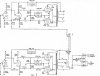
If you make the lower channel like the upper, and sever the link at R76, it would remove the balance check switch system.
it works completely different than I expected

st40.jpg
 
If you make the lower channel like the upper, and sever the link at R76, it would remove the balance check switch system.
it works completely different than I expected

View attachment 732377
Amazing, thanks! That's different from what I'd think as well. So my understanding is that I can sever the link at R76 and I'd be able to cut out the wiring to the switch altogether?
 
OK, does this also mean that I'll have to remove the centre channel terminal as well? Maybe this makes me a weirdo but I kind of find these types of idiosyncrasies charming in vintage equipment and so I'm not itching to get rid of it. But if it must be done then so be it.
 
Not the greatest news but it turns out I probably have a bad output transformer. Looks like I'll be hunting for a new pair this weekend. If anyone has any leads please let me know!
 
Last edited:
Not the greatest news but it turns out I probably have a bad output transformer. Looks like I'll be hunting for a new pair this weekend. If anyone has any leads please let me know!
Are you sure? The symptoms don't seem to suggest it.The Eico transformers are better than most.
If you connect pin 7 to pin 2 of each 7247 (12 dw7?) the volume may be lower, but it jumps out the tone control pecs.
If you had an external preamp you could connect pin 7 to the preamp and bypass everything but the amp.
If you were local I would offer my help
 
Last edited:
What makes you think the transformers are bad? Not impossible, but generally if one fails it'll go open coil on one side. They generally aren't super inclined to short or do odd things that take more involved measurements to test. Open winding is real simple to test, you'll just have no plate voltage on that particular tube, and an ohm meter will confirm that its dinked.
 
What makes you think the transformers are bad? Not impossible, but generally if one fails it'll go open coil on one side. They generally aren't super inclined to short or do odd things that take more involved measurements to test. Open winding is real simple to test, you'll just have no plate voltage on that particular tube, and an ohm meter will confirm that its dinked.
A few weeks back I got frustrated with the amp because for the life of me I still couldn't track down the cause of the issue. I'm pretty confident that if kept at it I could figure it out but being a work at home dad with a one year old I really didn't have the time. Plus, the baby was pretty bored of me staring at the thing and with the arrival of spring I figured our time would be better spent at the park. I took it to a local tech hoping for a quick solution. Here's what he emailed me yesterday:

"I have concluded that the secondary taps are damaged on one of the transformers also, there is grid leak emissions and shorts on one of the Rogers 7591's.

You will need at least one new OPT and a pair of 7591's.

I recommend using two matched OPT's as I mentioned before to keep AC balance in check and matched 7591 pair."
 
How exactly are the taps damaged? He may be right, but damage on the secondary side is extremely uncommon. I'd really want further specifics before transformer shopping.

Leakage on the tubes, yeah that can happen. Bad/worn output tubes in an old amp isn't really anything unusual.
 
How exactly are the taps damaged? He may be right, but damage on the secondary side is extremely uncommon. I'd really want further specifics before transformer shopping.

Leakage on the tubes, yeah that can happen. Bad/worn output tubes in an old amp isn't really anything unusual.
That's what I was thinking. I'm going to ask him to show me exactly where the damage is. Theoretically, what would damage like this sound like? Would it account for a drop in the volume of one channel?
 
About the only things that come to mind are open windings or internal shorts. An open you'd get no sound from. A short, that might show up as low volume but you'd have to do some testing to really determine if that was the case. It would need a little more than a quick ohm check I'd think. It could probably be determined by checking the transformer ratio and comparing to a known good example. That requires a voltage source, a good volt meter, and some math.
 
It could probably be determined by checking the transformer ratio and comparing to a known good example. That requires a voltage source, a good volt meter, and some math.

All quite within the capabilities of a tech. And why two 'matched OPTs'? Is it not possible to get a replacement that matches the one good one you already have?
 
Back
Top Bottom