• The move to the new server is done. There are some software and database maintenance updates in process. This has us passing the hat around to help out. We appreciate any donations. Seriously, even a dollar helps. The payment page may be found here - https://www.audiokarma.org/support.html

El34 / 12AX7 SE Build (My 1st build)

I am pretty sure now that I have a defective unit. Here is what the sine wave should look like when following the 'getting started' instructions using the flywires:
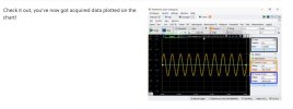
Self Test Instructions.jpg

Here is my result using the default settings per the instructions. Note no difinitive sine wave and the orange channel 1 is just vertical lines that cannot be adjusted at any range.
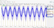
Self Test.jpg

Nothing is easy anymore. At least I think I wasn't the problem, nor the dummy load, BNC adapter or cables.
 
This is what I have tried. Tried 2 different computers with both the Diligent Waves and Audio Analizer Suite software installed. Tried 2 different amplifiers; my new build and my Dynaco ST70. I get the same results from all combinations. Even the Diligent Wave software will not give me a sine or square wave.

What is concerning is that when a 1kHz signal is sent to either amp with either computer, all transformers have an audible 1kHz tone coming from them. It will also get louder with more amplitude applied. This must not be an amp wiring or software issue. Yes, I am using an 8ohm dummy load. I think I followed all the connection instructions correctly. See below for my hookups.

View attachment 3612751
View attachment 3612753

I am totally baffled. This must be something stupid I am overlooking or I have a bad Analog Discovery 3.

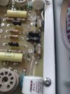
So the smoke I saw coming from the ST-70 bias meter was actually coming from the two 10 ohm resistors hidden under the meter. These resistors are on the ground circuit of the rca input jacks.

IMG20251028104647.jpg

I remember seeing a vid from Gabster talking about the problems with the Diligent BNC board and the way it handles grounds that could damage some amplifiers.

However, Skunkie used this setup to test her ST-70 builds. But I thought the use of the single BNC solved this problem. I now have both a Discovery 3 and 2 with both doing the same thing so the units must be good. The problem is elsewhere and I suspect I am the problem.

The ST-70 board is fried and new parts are on order. But I do not want to proceed until I know for sure what is going on. My ST-70 does have a bias meter that is always on but not sure if that has any bearing on the problem. Feeling disillusioned about now.
 
The Digilent BNC board only works with amps that have the speaker ground wires tied together (common ground) is my understanding. Amps that don't have the speaker wires grounded together are called (AI search info):

"An amplifier that does not ground the negative speaker wires together, or to the chassis, is commonly referred to as a bridged amplifier (or bridge-tied load, BTL) or a balanced amplifier. The negative speaker terminals on these amplifiers are often described as "floating" or "non-common ground". "

I would have guessed the ST70 uses a common ground on the speaker negatives and a Google search stated the original ST70s did use common ground. But, the same search also stated some ST70 upgrades, like installing a grounded three prong plug, did away with this common ground. Whether this is true or not.....IDK, never worked on an ST70. Maybe somebody more knowledgeable will chime in.
 
The Digilent BNC board only works with amps that have the speaker ground wires tied together (common ground) is my understanding. Amps that don't have the speaker wires grounded together are called (AI search info):
I can confirm that my ST-70 has common speaker jack ground for both channels.
 
This should not be a grounding problem with the amp outputs- this is a tube amp, each output winding is isolated electrically, so the output common will happily tolerate whatever voltage you want to call ground. I further assume that RCA input ground = speaker common ground.

Do you have a schematic of your modified ST-70? if we know the exact function of those burned resistors it might be a clue.

I always go back to basics. Using your voltmeter, what is the DC voltage of the discovery inputs and outputs vs common ground- is there a DC offset, or is everything centered on ground as you would expect. Burned resistors in the ground circuit of the amp input certainly seems to indicate a DC voltage coming from the discovery. Something cooked them. Is there an AC/DC differential between the ground of the ST-70 and the discovery ground?

Do you have a scope to check the test signals the discovery is outputting? Do the amplitudes match what you expect? Do you have a simple signal generator to pipe a signal into the discovery inputs and see if the display matches what you are outputting? There seems to be some big gremlin in there somewhere. Trust nothing, verify everything.
 
Do you have a schematic of your modified ST-70? if we know the exact function of those burned resistors it might be a clue.
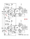
The amp board uses the original schematic. Per the board seller: "This was engineered to be a restoration board and as such, follows the original circuit EXCEPT for using the plentiful 6GH8A driver tube." Here is the schematic showing a red arrow to the burned resistors:

Board Schematic.jpg
Today I will do the self test from the Analog Discovery 'Getting Started' instructions again. I will do it for both the V2 and V3. First with the Digilent WaveForms software, then with the Audio Analiyser Suite software. The self test simply puts out a signal and shows as a sine wave in the scope window.
 
Wasn't sure what "D" was, just confirming for myself that it is the arbitrary chassis ground. I say arbitrary because in the original design the line cord was only 2 prong, and ground was an isolated floating island that was connected to the other isolated floating grounds of the sources. Under that original scheme, there should be not reason for current to flow from the RCA input ground to the chassis ground (let alone enough to cook those resistors), unless the discovery was outputting a large DC from signal to ground that cooked the resistor, hence my request to check for that DC voltage. There should not be one.

Was the amplifier modified to have an IEC connector, or otherwise have a 3-wire cord added that now tied the previously floating chassis ground to earth ground? Perhaps there is something that is causing the ground of the discovery (the ground of your computer) to be different than the ground of your amplifier? Different circuit, wiring error, etc? This is why you should use a meter to check for any AC/DC differences between these things.

You have used the discovery to look at itself, and have shown wonky results, this is why I am suggesting independent test devices- a voltmeter, and do you have a scope or alternative signal source other than the discovery?


Dynaco-ST70-Tube-Amp-Schematic.png
 
Was the amplifier modified to have an IEC connector, or otherwise have a 3-wire cord added that now tied the previously floating chassis ground to earth ground? Perhaps there is something that is causing the ground of the discovery (the ground of your computer) to be different than the ground of your amplifier? Different circuit, wiring error, etc? This is why you should use a meter to check for any AC/DC differences between these things.
Yes, an IEC was added. But I now think what might be going on. When I put the Discovery 3 on the ST70, it smoked. I then put the Discovery 2 on it to see if the same thing would happen and it did. But it may did so because it was initially damaged by the Discovery 3. Keep in mind that I never tried the Discovery 2 on the EL34 amp that I built because I just didn't know what was going on. More on this later.

I did some rigorous test today on both the Discovery 2 and Discovery 3. I did so testing with both the BNC adapter, flywire testing and both the Digilent WaveForms and Audio Analyzer Suite. Every possible combination imaginable. I got the same results from both the flywire hookup and BNC adapter thus ruling out that the adapter board was bad. I got a good sine wave from the Discovery 2 but a bad one with the Discovery 3 on one channel from both softwares.

Discovery 2 Wave Forms Test Flywire.jpg

Discovery 3 Wave Forms Test Flywire.jpg

At this point I decided to try the Discovery 2 and Audio Analyzer Suite on the EL34 build and got good results! Everything appears to be working and measuring as it should.

5K THD vs Frequency.jpg

I believe my EL34 amp was not damaged when I first tried the Discovery 3, because AAS would not allow a sweep if the distortion went too high. Not sure what was different with the ST70. But would you agree that the Discovery 3 has a defect?
 
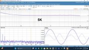
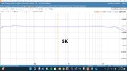
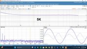
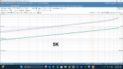
Back to the topic of this EL34 build. Now that I can use an analyzer, here are the results with the 5K primary OPT:

5K Frequency Response.jpg
5K THD vs Frequency.jpg
5K THD vs Power.jpg

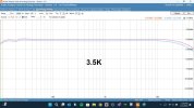
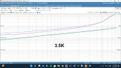
And results with the 3.5K primary OPT:

3.5K Frequency Response.jpg
3.5K THD vs Frequency.jpg
3.5K THD vs Power.jpg

Thoughts on 5K vs. 3.5K?
 
If you are reading this, reload it because I have made a couple of edits.

If you are using the same BNC adapter board with both Discovery 2 and 3, and it works for Discovery 2, the BNC board seems to be OK.

If you got good results for Discovery 2 and bad results for Discovery 3, Discovery 3 is bad.

However-
When I put the Discovery 3 on the ST70, it smoked. I then put the Discovery 2 on it to see if the same thing would happen and it did. But it may did so because it was initially damaged by the Discovery 3.

Let me get this right. D3+ST70 = smoke. You then replaced the smoked resistors with good ones? (or not, but then assuming the charcoal carcasses still worked), then D2+ST70 = more smoke. From the testing above, the Discovery 2 and the BNC adapter board is not the problem- you have a problem with the ST70, and its not because the resistors were previously damaged- smoke is smoke, and these resistors should NEVER smoke.

The only way those 10 ohm resistors would smoke is if you had either a very large AC or DC voltage with enough current behind it between the adapter board ground and the ST-70 chassis ground, which caused current to flow between the two grounds, smoking the resistor that connected them. Because you installed an IEC connector, ST70 ground is no longer floating, but tied to earth ground.

I have asked multiple times, and have not had an answer from you. Do you, with a voltmeter, see any AC or DC voltage appearing between the BNC Adapter board ground, and the ST-70 input/chassis ground when they are plugged in as before (but not connected)?
 
Last edited:
Let me get this right. D3+ST70 = smoke. You then replaced the smoked resistors with good ones? (or not, but then assuming the charcoal carcasses still worked), then D2+ST70 = more smoke. From the testing above, the Discovery 2 and the BNC adapter board is not the problem- you have a problem with the ST70, and its not because the resistors were previously damaged- smoke is smoke, and these resistors should NEVER smoke.
No, I tried the Discovery 2 before knowing the resistors were toasted. They were hidden under the bias meter. At that time I thought the smoke came from the bias meter. I haven't replaced any components other than the meter that I thought got toasted.

I haven't done the other testing you requested because once I found the burnt resistors, I didn't want to plug anthing more into the ST70. I came to a full stop. At this point the input board isn't even in the amp.
 
Until this can be resolved, it's a quick test to make sure you don't have a gremlin in your AC or amp wiring- measure between the BNC ground and chassis ground before you plug the signal into the input or you may smoke those resistors over and over.
 
Back to the topic of this EL34 build. Now that I can use an analyzer...


Thoughts on 5K vs. 3.5K?
Listen to both. I thought the 5K sounded better. I tested with two different transformers, a 3.5K and a 5K 15W CXSE Edcor at the time. The ISO might work better at 3.5K?

And yeah, the results from the AD3 look very whacked out!
 
Listen to both. I thought the 5K sounded better. I tested with two different transformers, a 3.5K and a 5K 15W CXSE Edcor at the time. The ISO might work better at 3.5K?
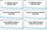
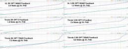
I have done a bunch of testing and listening. The results are mixed. The 3.5K sounded slightly better due to more 2nd harmonics but traded off much power. Adding feedback to Triode made it soundmore like UL and still got decent power. It was amazing to see the lack of 3rd order harmonics in 0 feedback Triode mode. I really liked triode when listening to string accoustics and female vocals. But gott muddy when listening to anything that had a 'wall of sound'. I think the difference between ISO and Edcor is probably the impedence ratios. It has been educational and here are some graphics:

THD vs. Frequency Compilation.jpg

THD vs. Power Compilation.jpg
 
Last edited:
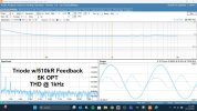
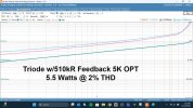
I did more listening and testing trying different feedback levels in Triode mode. I really like the UL sound with the OPT tapped at 5k and was hoping for better sound in Triode mode. The magical combination for my ears was using 510kR feedback for Triode. The ratio of 2nd and 3rd harmonics is more akin to that in UL mode interestingly. And basically identical to Triode with 750kR feedback with the 3.5k tap on the OPT. So I am now done.

Triode 510k Feedback 5K THD vs. Frequency.jpg

Triode 510k Feedback 5k THD vs. Power.jpg
 
Back
Top Bottom