

You are using an out of date browser. It may not display this or other websites correctly.
You should upgrade or use an alternative browser.
You should upgrade or use an alternative browser.
Electrolytic Capacitor Shoot-Out
- Thread starter patfont
- Start date


I used low impedance in most locations (per Oleg writeup). Nichicon UPW, UPJ, UPS. And UKL in low leakage. Left a couple orange elnas in the low leakage signal path on driver. Sounds very good. I've wondered since the start, being new to this, where UFG or Silmic etc should be tried. I followed the low impedance method. But maybe I should try them where I used low impedance??
Interesting. Electronics is a mystery to me. Maybe in some amps the audio signal is not filtered properly, or voltages are affected by using low impedance. It's the power supply board where this comparison started. And this is where I might try a different approach.

Mat86
Active Member
I've had good results with them (though usually they are part of a blend), and in fact I happen to be considering them for the last signal output caps on a project im doing. The one great thing about them is how compact they are while high voltage.Have you tried Audio Note Standard capacitors or would you recommend them?
"Global Negative Feedback Stage / Power Amp Feedback Path"
Value/voltage, unit?
Nichicon UES, the higher the voltage the better, but 16V is usually sufficient.
Quality designs also put back to back 1n4148 in parallel. If the amp fails and rails you do not want the full rail voltage imposed on the ecap unless it's rated for that voltage. If you think you can hear the sound of a shunt FB cap and are anal, put a film across it as well but imo it's a waste of time.
Value/voltage, unit?
Nichicon UES, the higher the voltage the better, but 16V is usually sufficient.
Quality designs also put back to back 1n4148 in parallel. If the amp fails and rails you do not want the full rail voltage imposed on the ecap unless it's rated for that voltage. If you think you can hear the sound of a shunt FB cap and are anal, put a film across it as well but imo it's a waste of time.

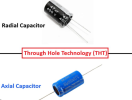
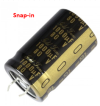
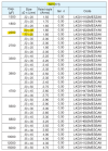
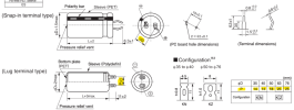
Nichicon KG capacitors have leads just like radial capacitors, just shorter, thicker, and preformed with a bend. Just look at the capacitor specs for the lead spacing and match it to the board through hole spacing. The new capacitors might be smaller so you may want to increase the voltage rating to get a larger diameter and lead spacing to match your board, but watch the height and diameter to make sure it will fit also.can Snap-in Nichicon KG capacitors be used instead of a radial- capacitor and wired into the holes
Are you confusing radial and axial capacitors with your question?
"Global Negative Feedback Stage / Power Amp Feedback Path"
Value/voltage, unit?
Nichicon UES, the higher the voltage the better, but 16V is usually sufficient.
Quality designs also put back to back 1n4148 in parallel. If the amp fails and rails you do not want the full rail voltage imposed on the ecap unless it's rated for that voltage. If you think you can hear the sound of a shunt FB cap and are anal, put a film across it as well but imo it's a waste of time.
Yes, it's best if the if the actual voltage is 1 volt or less and between DC and AC. Nichicon ES Bipolar capacitors are recommended.
If the DC voltage is higher than 3 or 4 volts, I prefer Elna Silmic II polarity capacitors only.
This is for me, and I'm staying away from other capacitors.

I just stumbled across this thread, and after just reading the first 20 pages, I've noticed many similarities to my own personal experiences and experiments doing these exact same substitutions (in complete isolation from this thread) within lots of different equipment during recaps for comparison's sake throughout the years. Namely, it can't all be tossed aside and dismissed as just being one person's subjective opinion. Specifically, with regards to:
1.) UKZ is one of the best all-around caps that works well (sounds good) in most any position that nobody is going to complain about. It's a great "go-to" cap for everything.
2.) Silmic II really do sound great, and not just in signal paths/ coupling. They sound good/ better even when other specs they do not possess should be prioritized instead. However, I'm going to disagree that RFS sounds better than UES. To me, personally, BP UES is the better sounding choice and my "go-to" for affordable, bulk capacitance < 1,000 uF with its much lower distortion (as long as my stock of it holds out). Important Note: The BP e'lytic's outer foil is connected to its shorter lead and acts as a shield from nearby noise and interference. If replacing polarized with BP, always make sure its shorter lead is connected to what was the negative side for better performance. Sure, it works either way but will be optimized for lower noise and a quieter background in this orientation.
3.) Audio caps with relatively poor specs do sound better more often in power supplies than other GP caps made specifically for PS and have huge impact for audio. GP caps made for PS are not made for audio PS in mind, but often lighting ballasts, etc. which have different requirements for current at both LF/ HF frequency extremes.
4.) Low-ESR, low-impedance or low-leakage electrolytics generally don't sound "better" even if the circuit asks for it. They usually result in some combination of artificiality, including but not limited to: thin, bright, lean, etched, over-emphasized, sibilant, etc. For me, anything relating to or effecting sound upon listening after is prioritized above all else. The ends justify the means. This, despite the fact studying the schematic may convince you there's no way it can cause the effect you're physically hearing and that an "audio cap" is unneeded/ a waste.
5.) The same series of cap behaves predictably across the frequency spectrum, so ones person's experience can largely be inferred to someone else with something else. For instance, Silmic II/ RFS will never be sibilant up top and will generally present the most bass/ midbass compared to many/ most alternatives. It is organic and more "tube" sounding. These are frequency response characteristics of this exact series of cap. Every electrolytic imparts its own frequency response characteristics to some degree.
6.) I recommend as much RFS and UES and possible to replace as much as possible, regardless of if you think low-impedance, low-ESR or low-leakage should be used instead because that's what was originally used or is recommended to use as a replacement. Sadly, many or most of these audio-rated, through hole caps have now been discontinued.
7.) The power filter caps do have a big effect on the audio signal as mentioned. I attribute much of this due to their emphasis (and available current at frequency extremes), despite not often being chosen for their "sonic attributes". I attribute a lot of this to their ripple current ratings at LF/ HF. Audio types are designed to sound more euphonic.
8.) I've taken to using as much BP electrolytics as possible lately where the capacitance is too large to use film instead, namely UES for everything, as far as I can. Sadly, they only go up to 1,000uF. BP types have much lower distortion which isn't even mentioned in datasheets but has big impacts for SQ (especially at volume) and should be prioritized more when choosing caps -especially electrolytics.
9.) Alternatively, wiring two of these BP caps in series produces much less distortion than a single BP type with the same capacitance -on par with PET/ film! under low voltage conditions with no DC bias voltage present. Capacitance is halved while doing this, so for instance, two 47uf bp 'lytics in series gets you close to around 22uF.
10.) Main Takeaway: It's not impossible to get great audio from GP types, it's just more of a crapshoot and less likely when directly compared to the best audio-rated alternatives. There are reliable consistencies and presentations of frequency response (i.e. dips/peaks/flat) within any given series of electrolytic capacitor at specific frequencies.
A couple other things: The more you replace vintage components on older equipment, the more "modern" it sounds. It begins to sound closer to how new equipment will sound. I see two reasons for this. 1.) A circuit may have a "sound" in itself, i.e. early solid-state "cap-coupled receivers" are still going to sound more "tube-like" with lower damping factors (bouncy bass) even after recapping them. 2.) But also, parts used to implement the circuit may have a "sound" in themselves that isn't very well understood or acknowledged but effects the signal heard, nonetheless. Caps are usually focused on, but replacing other components and material like transistors, diodes (1N to UF types), resistors (carbon-film to metal-film), inductors (iron-core to air-core) and wiring (pvc to ptfe/pp insulation) can also effect the sound and take it beyond what recapping alone can achieve. Alternatively, it's easier to sometimes achieve similar results using different cables instead.
Also, eventually, the point of diminishing returns kicks in. As an experiment, I once upgraded just about all the components and wiring in a preamp, just to see how far I could increase its performance beyond stock. What I found is that a surprising amount of benefit occured early on, with less improvement the more I replaced other components. I did the upgrades in stages with lots of listening in between. For those that say we're always biased to expect improvement regardless, sometimes, my "upgrades" didn't improve the sound and were removed. It's not the case that everything I always think will be an improvement is actually an improvement. The only way to know is to try, be honest about it and find out for yourself with lots of experimenting and listening. There is a sweet spot for upgrading material and you may not need to replace as much as you think to get the result you're after. Generally, it's kind of the opposite I've found. Replacing/ upgrading caps (especially old electrolytics) for starters usually takes care of most of the improvement that is noticeable.
CBB caps are an alternative to ECQ types and are always polypropylene>polyester by definition. They are available in the 50, 63V ratings in "capacitor kits" with many values. In these voltage ratings they have the correct 5mm lead spacing which makes them perfect for through-hole pcb work. However, they only go up to about 1uF. I highly recommend picking up a CBB kit to replace single-layer ceramics (which have decent HF characteristics but also distort, alot, and are therefore not really well-suited for audio). Tantalums also have very high distortion and are known for spectacular failure in some instances but some also like the way they sound and continue using them despite this. Alternatively, COG/NPO MLCC's are a great upgrade and improvement to SLCCs as well, in addition to polystyrene caps which are very heat-sensitive and destroyed using long soldering dwell times and not heat-sinking their leads first. However, if you can get them installed without damaging them, they almost always improve sound (where their effect may be audible within the circuit).
With regards to bypassing caps for better sound. I too have occasionally noticed the bypass cap doesn't always make the base cap sound "better" than before at which point I remove them. They form an LC (inductance-capacitance) circuit which can sometimes cause resonance and ringing at certain frequencies causing peaks and phase shifts. One thing to keep in mind is that the bypass cap should be of a superior material than its base cap. It doesn't really make sense to bypass a large electrolytic with a smaller one. You're looking to improve HF characteristics mainly, and this results from the capacitor material itself. The best film caps excel at high frequency performance compared to electrolytics -which is one of the main weaknesses of electrolytics -even after a recap. Within film capacitors and film insulation in cables, there's a hierarchy of performance as it relates to tan delta/ dissipation factor as well as their dielectric performance characteristics -the lower the better for dielectric constant, dielectric absorption and dielectric loss, starting at polyester for capacitors and pvc for film insulation with both ending with teflon with several other choices in between. In many ways and from my direct experience, film impacts the performance ceiling of your equipment -whether you think it is having that effect or not. This is why different cables and different film capacitors effect sound.
1.) UKZ is one of the best all-around caps that works well (sounds good) in most any position that nobody is going to complain about. It's a great "go-to" cap for everything.
2.) Silmic II really do sound great, and not just in signal paths/ coupling. They sound good/ better even when other specs they do not possess should be prioritized instead. However, I'm going to disagree that RFS sounds better than UES. To me, personally, BP UES is the better sounding choice and my "go-to" for affordable, bulk capacitance < 1,000 uF with its much lower distortion (as long as my stock of it holds out). Important Note: The BP e'lytic's outer foil is connected to its shorter lead and acts as a shield from nearby noise and interference. If replacing polarized with BP, always make sure its shorter lead is connected to what was the negative side for better performance. Sure, it works either way but will be optimized for lower noise and a quieter background in this orientation.
3.) Audio caps with relatively poor specs do sound better more often in power supplies than other GP caps made specifically for PS and have huge impact for audio. GP caps made for PS are not made for audio PS in mind, but often lighting ballasts, etc. which have different requirements for current at both LF/ HF frequency extremes.
4.) Low-ESR, low-impedance or low-leakage electrolytics generally don't sound "better" even if the circuit asks for it. They usually result in some combination of artificiality, including but not limited to: thin, bright, lean, etched, over-emphasized, sibilant, etc. For me, anything relating to or effecting sound upon listening after is prioritized above all else. The ends justify the means. This, despite the fact studying the schematic may convince you there's no way it can cause the effect you're physically hearing and that an "audio cap" is unneeded/ a waste.
5.) The same series of cap behaves predictably across the frequency spectrum, so ones person's experience can largely be inferred to someone else with something else. For instance, Silmic II/ RFS will never be sibilant up top and will generally present the most bass/ midbass compared to many/ most alternatives. It is organic and more "tube" sounding. These are frequency response characteristics of this exact series of cap. Every electrolytic imparts its own frequency response characteristics to some degree.
6.) I recommend as much RFS and UES and possible to replace as much as possible, regardless of if you think low-impedance, low-ESR or low-leakage should be used instead because that's what was originally used or is recommended to use as a replacement. Sadly, many or most of these audio-rated, through hole caps have now been discontinued.
7.) The power filter caps do have a big effect on the audio signal as mentioned. I attribute much of this due to their emphasis (and available current at frequency extremes), despite not often being chosen for their "sonic attributes". I attribute a lot of this to their ripple current ratings at LF/ HF. Audio types are designed to sound more euphonic.
8.) I've taken to using as much BP electrolytics as possible lately where the capacitance is too large to use film instead, namely UES for everything, as far as I can. Sadly, they only go up to 1,000uF. BP types have much lower distortion which isn't even mentioned in datasheets but has big impacts for SQ (especially at volume) and should be prioritized more when choosing caps -especially electrolytics.
9.) Alternatively, wiring two of these BP caps in series produces much less distortion than a single BP type with the same capacitance -on par with PET/ film! under low voltage conditions with no DC bias voltage present. Capacitance is halved while doing this, so for instance, two 47uf bp 'lytics in series gets you close to around 22uF.
10.) Main Takeaway: It's not impossible to get great audio from GP types, it's just more of a crapshoot and less likely when directly compared to the best audio-rated alternatives. There are reliable consistencies and presentations of frequency response (i.e. dips/peaks/flat) within any given series of electrolytic capacitor at specific frequencies.
A couple other things: The more you replace vintage components on older equipment, the more "modern" it sounds. It begins to sound closer to how new equipment will sound. I see two reasons for this. 1.) A circuit may have a "sound" in itself, i.e. early solid-state "cap-coupled receivers" are still going to sound more "tube-like" with lower damping factors (bouncy bass) even after recapping them. 2.) But also, parts used to implement the circuit may have a "sound" in themselves that isn't very well understood or acknowledged but effects the signal heard, nonetheless. Caps are usually focused on, but replacing other components and material like transistors, diodes (1N to UF types), resistors (carbon-film to metal-film), inductors (iron-core to air-core) and wiring (pvc to ptfe/pp insulation) can also effect the sound and take it beyond what recapping alone can achieve. Alternatively, it's easier to sometimes achieve similar results using different cables instead.
Also, eventually, the point of diminishing returns kicks in. As an experiment, I once upgraded just about all the components and wiring in a preamp, just to see how far I could increase its performance beyond stock. What I found is that a surprising amount of benefit occured early on, with less improvement the more I replaced other components. I did the upgrades in stages with lots of listening in between. For those that say we're always biased to expect improvement regardless, sometimes, my "upgrades" didn't improve the sound and were removed. It's not the case that everything I always think will be an improvement is actually an improvement. The only way to know is to try, be honest about it and find out for yourself with lots of experimenting and listening. There is a sweet spot for upgrading material and you may not need to replace as much as you think to get the result you're after. Generally, it's kind of the opposite I've found. Replacing/ upgrading caps (especially old electrolytics) for starters usually takes care of most of the improvement that is noticeable.
CBB caps are an alternative to ECQ types and are always polypropylene>polyester by definition. They are available in the 50, 63V ratings in "capacitor kits" with many values. In these voltage ratings they have the correct 5mm lead spacing which makes them perfect for through-hole pcb work. However, they only go up to about 1uF. I highly recommend picking up a CBB kit to replace single-layer ceramics (which have decent HF characteristics but also distort, alot, and are therefore not really well-suited for audio). Tantalums also have very high distortion and are known for spectacular failure in some instances but some also like the way they sound and continue using them despite this. Alternatively, COG/NPO MLCC's are a great upgrade and improvement to SLCCs as well, in addition to polystyrene caps which are very heat-sensitive and destroyed using long soldering dwell times and not heat-sinking their leads first. However, if you can get them installed without damaging them, they almost always improve sound (where their effect may be audible within the circuit).
With regards to bypassing caps for better sound. I too have occasionally noticed the bypass cap doesn't always make the base cap sound "better" than before at which point I remove them. They form an LC (inductance-capacitance) circuit which can sometimes cause resonance and ringing at certain frequencies causing peaks and phase shifts. One thing to keep in mind is that the bypass cap should be of a superior material than its base cap. It doesn't really make sense to bypass a large electrolytic with a smaller one. You're looking to improve HF characteristics mainly, and this results from the capacitor material itself. The best film caps excel at high frequency performance compared to electrolytics -which is one of the main weaknesses of electrolytics -even after a recap. Within film capacitors and film insulation in cables, there's a hierarchy of performance as it relates to tan delta/ dissipation factor as well as their dielectric performance characteristics -the lower the better for dielectric constant, dielectric absorption and dielectric loss, starting at polyester for capacitors and pvc for film insulation with both ending with teflon with several other choices in between. In many ways and from my direct experience, film impacts the performance ceiling of your equipment -whether you think it is having that effect or not. This is why different cables and different film capacitors effect sound.
Last edited: