• The move to the new server is done. There are some software and database maintenance updates in process. This has us passing the hat around to help out. We appreciate any donations. Seriously, even a dollar helps. The payment page may be found here - https://www.audiokarma.org/support.html

EMIT & EMIM Tweeter Diaphragm Repair How To

ktpma said:
i do have problem in my Qe speaker emit tweeter ,
imposible to replace other type of tweeter like horm type? or other type ? i not known much in this,if can replace what is the watt ? i have see the repair guide ,thanks and useful but mine is beyond the repair . i need buy new diaphragm so expensive .but i like to keep this my old buddy too long with me , please help me to save .

thanks all of u.....

Hello ktpma......welcome to Ak. All the way from Singapore eh? Good stuff. The world is a small place now with the internet. I think you'll find this a worthwhile site to be a member of.

A few questions. (1) Why do you say the tweeters are beyond repair ? (2) Are you able to get replacement diaphragms in your area? They are approx 50 $US from the states. How much in your area? (3) what about Ebay or other used sources? Have you looked there?

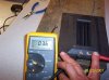
I've measure the DC resistance on this diaphragm and it measures about 3.7 Ohms. Omi measured 3.2 Ohms on his, so a good guess would be that you would have to replace the tweeter with a 4 Ohm impedance driver. Unless someone else has done this exact replacement, I think it is very hard to advise you on what replacement driver will work. There are many factors that come into play, and the crossover point has to be matched (2,500 Hz according to the spec sheet at http://www.infinity-classics.de/infinity/manuals/Qe_technical_sheet.pdf ). You may into experimental territory here.

But, wait a while, and more members may reply with more information.
 
Hello Kencat ...
thank for ur care and internet too. Ans (1) ribbon are cut badly and lost some part.(2) price approx S$90 for 1pc (3) can't see in ebay .i take ur advise and wait some one guidance...
thank alot
 
Emit Repair

Ken
Just read your post on repairing the emit tweeters. That's pretty cool that you actually get inside them like that. Looks like you repair was near the edge of the ribbon. That would be a real nasty job if it were some type of voice coil with a million turns. Your repair looks like it was on the edge of the ribbon and not somewhere in the middle. I have also heard of using a rear window de-icer kit to repair the coil itself. Another option might be to use conductive pin (CW2200STP). It is mainly used for repairing circuit boards and has high silver content, which makes it very conductive. I think the less mass you add especially towards the middle, the better off you are.
Adding to much weight would affect the high freq. response of the tweeter. They also make solider that has a high silver content. It might be more expensive than the regular stuff but it flows much better. I use to use it for repairing medical electronics that had surface mount components. Anyway nice job and great pictures.
 
Hail,
Seeing that there are some EMIT's and EMIM's for sale ATM, I pose the following question; do the EMIT's or EMIM's themselves actually break, making back up's beneficial, or is it just the diaphragms?
Vito
 
Vito,

There is not much to go wrong with the framework and magnets that I can see. JP (Charivari) did report some magnet breakage I think (after some unplanned whackamoles with taking Emits apart IFRC) in a post of his.

The diaphragm is the most likely culprit for failure....the solder joint, or the "racetrack"/ "windings" being broken. Problem is, the diaphragms are hard to get. Not made anymore I don't think.

So.....the diaphragms are best obtained with the entire unit I quess.....unless there are still some sources of the diaphragms still out there.
 
Here goes another Thank you to kencat. I bought a pair of foster ribbon tweeters today which are essentially the same thing as an emit. First did not work at all, upon taking it apart this tweeter had a rough life it was smoked. Checked the solder joints and nothing, did a little more digging and found a busted lead, little bit of soldering and bang zoom it works now. Second was dead, hit the solder joints and houston we have lift off.
Never give up never surrender
 
Measured the resistance on one of my emits today and got a reading of 30ohms.
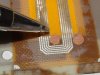
Decided to try some of that liquid copper stuff that is used in rear window defogger repair kits. After prepping the area with a little sand paper, I coated the joint where the electrical connection meets the ribbon track. I let it dry for a few minutes and re-measured and got 6 ohms. Thought if this worked it would be an easier fix that using an iron. Anyway here are my words of wisdom, very inportant to use some type of jig or longer screws as mentioned eailer in this thread. THiswill keep the spacers from moving around as your putting it all back together, otherwise you get something like the picture below. Oh well, hard lesson learned. Anyway I will try the liquid copper again as I am sure I will find at least one more bad unit on the other qls-1.

Banff
 

Attachments

  • dmg2.JPG
    dmg2.JPG
    126.3 KB · Views: 512
  • dmg3.JPG
    dmg3.JPG
    125.9 KB · Views: 518
The broken magnets must be replaced. They make new north-souths that wont go back together again. Maybe you can get away with putting one that was only broken in half back, but from my experience, and I have seen them in 7 or more pieces and it don't work. I used to repair them under warranty in the 70's and 80's. Good luck.
 
EMIM Repair

I had a couple of emim's go out on my RS 4.5's the other night, swapped a pair out of my RS 2.5's so I still have tunes, thankfully.

So today reread the emit repair thread and decided tonight I'd screw up my courage and at least try to see what was the problem. One measured 68Ω's and the other 45Ω's so I had a feeling they weren't toast since I still had some resistance.

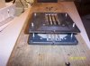
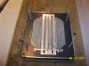
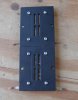
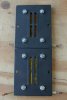
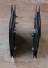
There are six screws that hold them together that use a cap type of nut with a shallow phillips head. I loosened them before I made a crude fixture out of a 2x10. I took the four screws on the sides completely out. Them grabbed some 16 penny nails and nailed the emim with contacts down to the board leaving about 1.5" roughly above the emim. Cut the nail heads off with a bolt cutter. Which gave me enough room to slide the emim up enough to get the last two screws out. I carefully lifed the top section off enough to see that there are two more brass screws that bolt into the board that holds the mylar in place and makes contact via a wire to the external leads see picture.

Lifting up enough to get the 1/4" brass nuts off the front came off with out problem. I cleaned up the bolts and nuts with brasso (took about an hour). Put the assembly back together which was a PITA to get the tiny nuts back on. I took a measurement a crossed the screws before I put it back together and got 3.4Ω's but once I put it back together it read 7.6Ω's Better but not good enough, should have removed the brass nuts that hold the external leads on and cleaned them I guess...

When I get another chance I'll tear it back down and go and find new nuts and bolts and try again. Corrosion is definitely the enemy...
 

Attachments

  • 100_1665.jpg
    100_1665.jpg
    154.8 KB · Views: 364
Good news, replacing all the screws which were 4-40 thread by 1/4" long on the mylar board and 3/8" long for the terminals resulted in a working emim :thmbsp:

I also took Ken's advice and hit the solder joints on the lead wires and polished the terminals with brasso.
 

Attachments

  • 100_1666.jpg
    100_1666.jpg
    147.9 KB · Views: 503
  • 100_1667.jpg
    100_1667.jpg
    139.5 KB · Views: 494
  • 100_1669.jpg
    100_1669.jpg
    110 KB · Views: 443
  • 100_1671.jpg
    100_1671.jpg
    147.1 KB · Views: 429
  • 100_1670.jpg
    100_1670.jpg
    184.3 KB · Views: 444
the idea behind the nails?? is that to keep everything lined up. i did hear something about having to press both sides together because of the magnets. supposed you just took it apart??. would you be able to get it back together by your self or you would need help.
 
what about these from orange county speaker, wouldent they work for anybody looking for a replacment??.
 

Attachments

  • emim-dia-f66.jpg
    emim-dia-f66.jpg
    11.6 KB · Views: 249
the idea behind the nails?? is that to keep everything lined up. i did hear something about having to press both sides together because of the magnets. supposed you just took it apart??. would you be able to get it back together by your self or you would need help.
These drivers use very powerful rare earth samarium cobalt magnets (the HE versions use neodymium) that react faster and more strongly than whoever is taking apart the drivers. Were they just pushing the halves apart, that wouldn't be such an issue. The trouble is that while the magnets repel when aligned, they strongly attract when slightly off to the side. So, when the screws are removed on one of these drivers without the nails (or longer screws to ease the halves apart as per my preference), one half will move in relation to the other and both will snap together with significant force. This results in not only very pinched fingers and a subsequent difficulty in prying the halves apart, but the movement also tends to shred the diaphragm. In some cases, the glue holding the magnets has sufficiently weakened that the shearing-snapping process can break some magnets loose and they subsequently can shatter during this unfortunate happening.

Simply put, don't attempt disassembling an EMIT and especially not an EMIM without some means to keep the halves aligned else you'll likely have an irreparably damaged driver and very sore finger tips.

- JP
 
what about these from orange county speaker, wouldent they work for anybody looking for a replacment??.
They should work fine, but they are costly. Why outlay the money when the existing diaphragm can be made good as new with a little effort that's equivalent to what would be needed to install the replacement anyways?

- JP
 
i was just thinking for someone who had emim,s that needed a new diaphragm. i know they are costly,but if you needed one, its better then nothing. thanks for the info. my 1b's are working well now, but hey,you never know
 
How to make a DIPOLE EMIT in easy steps

Why Arnie Nudell and Infinity never made any DIPOLE EMITs is beyond me. The design of the EMIT is just like the EMIM and you all know how well the EMIM works as a dipole speaker. Well the EMIT will work the same way as well.

http://launch.ph.groups.yahoo.com/group/InfinityClassics/photos/view/2a95?b=1&m=s&o=0

Follow this link I previously posted on the Yahoo Infinity Forum on how to take 2 normal monoplar EMITs and reassemble them as a single dipole EMIT.

I know this can get expensive as for every one dipole EMIT you want to make you need to start out with two monopole EMITs...but believe me the time, expense and effort is worth it.

To date I have never heard a better tweeter than a DIPOLE EMIT and I have been making them for over 25 years.

I have made hundreds and have them out in the field in many of my speakers and everyone swears by them.

I am sure you will too.

This thread is also helpful for anyone wanting to take apart and repair any EMIT driver as it is all explained in easy pictural format.

If anyone has problems accessing these pictures let me know and I will sent them to you directly via E-mail or repost them here on this forum.

Finally note:

The tall 7 inch EMITs (like in the Quantum Series) are called FULL LINE SOURCES and should measure about 5 Ohms

The short 3.5 inch EMIT's (like in the IRS and RS Series) are called 1/2 LINE SOURCES and should measure about 3 Ohms.

Any EMIT that measures significantly different than these DC resisitance values is an EMIT that is malfunctioning. Sometimes resoldering the connections, as pointed out above, will fix the problem, but please be careful.

Also not all broken magnets need to be replaced. Superglue and epoxy are very effective at putting them back together and once reattached they function just fine. (you need to coat them with standard mylar "Scotch" tape to prevent shorts against the diaphragms - most original units used YELLOW mylar tape - if it comes off or bubbles you need to replace it)

Also for those of you that need magnets or spare parts I have a house full of them. I can usually help with most EMIT repairs.

O.K.

MichaelAlanMarks@aol.com
pm me for my phone number.
 
Last edited by a moderator:
Dipole EMIT Pictures

Here are some representative pictures of what my DIPOLE EMIT tweeters look like when they are done. Realize it take two normal tweeters to make one of these. So in these pictures where I show a pair....I actually had to start with 4 of them to make these two. Any questions just ask. These are just wonderful to listen to.....much better than the normal EMIT tweeter but your cabinet design must be capable of accomodating the DIPOLE design to make use of them.

For now.


AKA: MagicMarksy on eBay
 

Attachments

  • DSCN2622a.jpg
    DSCN2622a.jpg
    70.3 KB · Views: 309
  • DSCN2623a.jpg
    DSCN2623a.jpg
    60.3 KB · Views: 266
  • DSCN2624a.jpg
    DSCN2624a.jpg
    66.5 KB · Views: 336
  • DSCN2625a.jpg
    DSCN2625a.jpg
    54.6 KB · Views: 238
  • DSCN2626a.jpg
    DSCN2626a.jpg
    45.9 KB · Views: 256
Last edited by a moderator:
I can't find a speacific thread about this so I'll just ask for HELP! here.

I have a buzzing EMIM in my RS4.5. It is infrequent,mild and only shows up during loud piano passages or during some random note. Is there a way to stretch the diaphram tighter? Thanks!!!
 
I've heard that heating up the ribbon element with a hair dryer can tighten up the plastic mylar ribbon. You can also try to manually stretch the element, but that's a very delicate operation.
 
Great posts in this thread. Very informative indeed.

I had an emit on one of my QLS that was very low output. It worked, but was not very loud. So after reading this thread I decided to take it apart and check it out. What has me confused is that the membrane read zero ohms when I tested it. I pulled two other emits (but did not remove the membrane) and they both read zero as well. I went ahead and did the solder button melt as suggested by Kencat. I also tried the hair dryer trick, which smoothed things out a bit. I put everything back together and noticed some improvement.

I can't figure out why I'm getting zero ohm readings, however. I checked my meter and it is functioning correctly. I stick the probes on the solder buttons - zero. I stick the probes on the terminals for the wires - zero. What am I doing wrong? Any ideas?:scratch2:
 
Back
Top Bottom