• The move to the new server is done. There are some software and database maintenance updates in process. This has us passing the hat around to help out. We appreciate any donations. Seriously, even a dollar helps. The payment page may be found here - https://www.audiokarma.org/support.html

Fisher 480a questions

Tom,
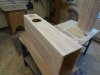
Great looking frame, nice joinery. But you closed off some of the ventilation holes and that amp will get hot, especially now that it is dissipating additional power that would have been used by the disconnected tuner.
Make sure the amp sits well off the ground on tall feet with a well ventilated bottom cover.
For the poor man's variac-you're supposed to start with a low watt bulb (in series) and gradually increase the bulb wattage. I couldn't tell you where to stop because I use a variac. If you can't find a 200 w incandescent bulb, you can always wire two 100 w bulbs in series.
Rich
 
Thinking the same thing

Tom,
Great looking frame, nice joinery. But you closed off some of the ventilation holes and that amp will get hot, especially now that it is dissipating additional power that would have been used by the disconnected tuner.
Make sure the amp sits well off the ground on tall feet with a well ventilated bottom cover.
For the poor man's variac-you're supposed to start with a low watt bulb (in series) and gradually increase the bulb wattage. I couldn't tell you where to stop because I use a variac. If you can't find a 200 w incandescent bulb, you can always wire two 100 w bulbs in series.
Rich

Rich,

I was thinking that too regarding the vent holes. I may just drill some, I have some 3/4" standoffs for feet, so that will help. The frame is just dry fitted now, the nice thing about this chassis is where it bends 90 degrees. I cut a small kerf in the trim and the wood stays in place all by itself without any adhesive. I'd like to pick up a fisher badge somewhere to put on the front of it, no luck on eBay yet. I have just carve it myself with a wood burning gun.

I have a variac as well, but no meter on it. Someone told me it was best to power up on a dim bulb tester before using the variac? I have read to use 1.5 X the wattage of the radio/amp.. A 40 watt works on an old Zenith radio I had.

I am the high bidder on those Caps you recommended, and I have the rest of the stuff coming from mouser. I decided to wait on changing out the sockets for now since I'm going to be using 4-40 screws to hold the tensioners in place and it will be easy to change them out in the future when I can pick them up at a swap meet and I can look at them in person.

-Tom
 
A bit of advice I read about restoring old amps
1. When measuring voltages on a powered piece of equipment, keep one hand behind your back as you work or probe with the other. If you're holding the chassis (ground) with one hand and your other hand slips and catches a shock-the current can pass through your heart and kill you. Remember..one hand behind your back.
2. The first time you power on your newly completed project, you should treat it with the same respect that you would treat a bomb, because it might blow up in your face. I actually switched on my first project from under my workbench, and that was before I even read that recommendation. That's why you bring up the power slowly with a variac..you'll hear it sizzle and smell it burning as the voltage rises if there's a problem. This only works well for solid state rectified power supplies like in the 480/481. Tube rectifiers don't start conducting until they hit a certain voltage. I use my "poor man's variac" along with my variac because it alerts me it there's a short.

Get the two books by Morgan Jones if you have an aptitude for this stuff. If you're like me, you'll soak it up like a sponge.
 
Got it.

A bit of advice I read about restoring old amps
1. When measuring voltages on a powered piece of equipment, keep one hand behind your back as you work or probe with the other. If you're holding the chassis (ground) with one hand and your other hand slips and catches a shock-the current can pass through your heart and kill you. Remember..one hand behind your back.
2. The first time you power on your newly completed project, you should treat it with the same respect that you would treat a bomb, because it might blow up in your face. I actually switched on my first project from under my workbench, and that was before I even read that recommendation. That's why you bring up the power slowly with a variac..you'll hear it sizzle and smell it burning as the voltage rises if there's a problem. This only works well for solid state rectified power supplies like in the 480/481. Tube rectifiers don't start conducting until they hit a certain voltage. I use my "poor man's variac" along with my variac because it alerts me it there's a short.

Get the two books by Morgan Jones if you have an aptitude for this stuff. If you're like me, you'll soak it up like a sponge.


1. Good advice! I try to keep one hand in my back pocket at all times, makes working a bit more complicated, but I'm a chicken ****. Lol.

2. :) I'm going to turn on the power switch with a really long stick from across the room while wearing a leather welding smock and helmet! JK, but I will be careful. I plan to use the Variac as well as the dim bulb.
I am familiar with working on low voltage surface mount stuff, 0402 packages (which are tiny) and very safe. This is just my first real "kill you voltage" stuff I've worked on.

I ordered the first book, "Valve Amplifiers" by Morgan Jones, ($80 BUCKS!) hasn't got here yet. I did read the first part of it on Amazon and find it to be written in a manner that I can learn from. I'm glad it's not filled with all the math that's required, that would have me glazed over in about two pages. It's a good investment for me as I really am enjoying this hobby, and when I get into something, I go a little crazy with it..(like owning about 12 turntables).

-Tom
 
Cooling

Rich,

I'm trying to solve the issue with ventilation of the amp chassis (trim blocking the vent holes). I'm thinking of mortising in a small 12V fan into the back side of the wood and perforating the wood underneath.
I will give the fan is own power supply and plug into power conditioner, but I'm really unsure if tube technology is prone to picking up noise from a fan? What do you think of this idea? See pic*

Also, a guy at work asked me if I wanted him to design a PCB that will shut power down to the amp when not in use. He said he could make something small, about 1"x2" that could mount under the chassis. I'm skeptical because I really don't want to complicate things.. Maybe I'll take him up on it down the road.

-Tom
 

Attachments

  • image.jpg
    image.jpg
    60.5 KB · Views: 16
Tube amps usually sound better as they warm up, so I wouldn't bother shutting it down automatically unless you regularly fall asleep with it on. Even then, you could do it more simply with an off the shelf device.
My gut tells me the amp will pick up noise from the fan. Even if the fan is DC it will have a commutator. I think passive ventilation is fine, you just have to make it available.

What you might want to consider building is a bucking transformer-it reduces today's line voltage to the voltage these amps were designed for. That's going to be one of my next projects.
Again..nice joinery. A fellow woodworker too?
 
Tube amps usually sound better as they warm up, so I wouldn't bother shutting it down automatically unless you regularly fall asleep with it on. Even then, you could do it more simply with an off the shelf device.
My gut tells me the amp will pick up noise from the fan. Even if the fan is DC it will have a commutator. I think passive ventilation is fine, you just have to make it available.

What you might want to consider building is a bucking transformer-it reduces today's line voltage to the voltage these amps were designed for. That's going to be one of my next projects.
Again..nice joinery. A fellow woodworker too?


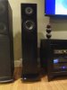
Fellow woodworker? Yes sir! love working with wood, its great when i can combine the two hobbies. For instance, these speakers that I made.
 

Attachments

  • DSC04338.jpg
    DSC04338.jpg
    52.9 KB · Views: 17
  • DSC04339.jpg
    DSC04339.jpg
    48.6 KB · Views: 17
  • DSC04407.jpg
    DSC04407.jpg
    41.6 KB · Views: 17
Oops

Nice looking inputs. When you get the tube retainer springs I believe you'll have to drill out the rivets holding the existing sockets. If you ever considered changing the sockets to high end sockets, now would be the time. Note though that not all sockets are oriented the same way relative to the screws.
These are nice caps:
http://www.ebay.com/itm/4x-Vintage-...pt=Vintage_Electronics_R2&hash=item338ea49131

Rich,

I won these caps, but I think we missed a decimal point. Just paid for them and I see they are .0047 uF aren't the coupling caps .047? Guess I'm going to have some great old caps in my bin for a future project and will start looking for the .047 again.

-Tom
 
I don't expect you'll have much trouble out of the amp if the holes aren't all open. Most amps didn't even have those. If you have some gap underneath so it can draw air in, that ought to be plenty if the sides are closed off. I suspect you'll hear more mechanical noise from the fans than anything else.
 
Concur with Gadget on cooling. None of my el-84 FISHERS have cooling holes on the sides. And they live in consoles, so the retained heatload is a lot more than a standalone. Either make some wood block feet or get some plastic feet to attach to the chassis. I would suggest a metal plate underneath for shielding and protection from fingers. Some metal mesh like used for cabinet grille's would work for the finger and venitlation plus giving some shielding. The fan's aren't needed.
 
Shoot, wrong caps-my bad.,
I'll call you tomorrow to get your home address and I'll send you some caps for your amp. (They are nice caps though!)
Really sorry about that. Rich

Larry-
When you make that amp Stand Alone, that 250 ohm 10 watt resistor is there to make up for the power that normally would be used by three 12ax7s in series in the tuner chassis. They really emits some heat in the Stand Alone Chassis, much too hot to touch (you will get burned) and hot enough that the print burns off. I even tried a surface mount resistor on one of my amps but the chassis got too hot. The Stand Alone amp definitely runs hotter than your console amp because it has to get rid of the power that normally would be used for the attached tuner. Trust me, my amps get hot right over the resistor-that's why I re-located it under some vent holes. There's another thread elsewhere regarding the conversion to Stand Alone-the author simply placed that resistor under the twist caps. The reason I re-located them was because the caps became too hot. Regarding the location of the side vent holes, they're near the tubes, which need airflow if you want them to have a long life. At the very least, the amp must be as open as possible underneath and up on tall feet to promote airflow by convection. After conversion to Stand Alone, that was my main amp for over a year-I know it well and it's a heater.
Rich
 
Shoot, wrong caps-my bad.,
I'll call you tomorrow to get your home address and I'll send you some caps for your amp. (They are nice caps though!)
Really sorry about that. Rich

Larry-
When you make that amp Stand Alone, that 250 ohm 10 watt resistor is there to make up for the power that normally would be used by three 12ax7s in series in the tuner chassis. They really emits some heat in the Stand Alone Chassis, much too hot to touch (you will get burned) and hot enough that the print burns off. I even tried a surface mount resistor on one of my amps but the chassis got too hot. The Stand Alone amp definitely runs hotter than your console amp because it has to get rid of the power that normally would be used for the attached tuner. Trust me, my amps get hot right over the resistor-that's why I re-located it under some vent holes. There's another thread elsewhere regarding the conversion to Stand Alone-the author simply placed that resistor under the twist caps. The reason I re-located them was because the caps became too hot. Regarding the location of the side vent holes, they're near the tubes, which need airflow if you want them to have a long life. At the very least, the amp must be as open as possible underneath and up on tall feet to promote airflow by convection. After conversion to Stand Alone, that was my main amp for over a year-I know it well and it's a heater.
Rich

No worries Rich, I found some similar ones at .047 and bought them "buy it now".
I suspect you are right Gadget, I found some conical feet about 1.5" tall that I will be using for feet that will create a gap. These are speaker spikes, but I will file them down a bit. This chassis normally sat on a piece of wood with no air flow under it, so I thing once it is open on the bottom it should be ok.
Just have to find a suitable grille to keep fingers out.

-Tom
 
If heat from the resistor is an issue, maybe using one that bolts to the chassis to make it a heat sink would be a good idea. The chassis would get warm, but I expect it ought to be better than retaining all of that heat underneath.


If you really wanted to get into it, you could eliminate the bias adjustment thing and just ground those grid resistors like a normal cathode bias amp. That would result in a smaller cathode resistor and less heat, probably about a 100 ohm 10 watter. You would really need 7189's though. The 6bq5's are already running well past ratings at effectively 360v on the plates (plate - cathode voltage). Without the bias rig, you'd probably be closer to 375. A 6bq5 is rated for 300.

If you wanted to retain a bias adjustment, some changes to the values could be done to have a smaller cathode resistor and less positive grid voltage, but still have some amount of adjustment. The stock design was made the way it was just to get enough voltage to run the 12AX7's in the tuner. There is no real need to have the cathode at 33v vs say 15v without them.

You could also convert it to straight up fixed bias and eliminate that resistor entirely. Back to needing 7189's though since with a grounded cathode, you're at higher effective plate voltage. There does appear to be an extra heater winding for the tuner that will not be used anymore if the amp is standalone. It would be a small matter to build a voltage doubler or tripler to get enough DC to work as a bias supply.


I'm just chucking out thoughts here. I don't actually own one of these, but its fun looking at possibilities sometimes.
 
Gadget,
I tried a surface mount resistor on one of my amps and the chassis was burning up. On this chassis, there's only one place to put a surface mount resistor, which is on the side wall under the Mains transformer. I didn't like how hot the chassis got, which conducted heat to the attached Mains transformer, which I thought might not be a good idea. In fact, the mains transformer was warmer on the amp with the surface mount resistor than on the amp with the through hole resistor mounted below the top surface vent holes. I thought about an external heat sink with fins to improve the dissipation by convection, but I didn't think I'd like the appearance.
Rich
 
i think I'm ready

i think I'm ready Rich! got my resistors today, along with a few caps..

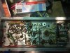
Does this look right? I soldered the 250 ohm to the chassis, then up to the test point in the molex connector.

should i use the dim bulb tester in conjunction with a variac? with tubes in it or without? With speakers connected i assume?
 

Attachments

  • IMG_0882.jpg
    IMG_0882.jpg
    110.5 KB · Views: 30
  • IMG_0883.jpg
    IMG_0883.jpg
    110.7 KB · Views: 37
  • IMG_0880.jpg
    IMG_0880.jpg
    97 KB · Views: 31
It's Alive!

Wow!!! It actually worked! I got to listen to it for a few minutes, then got a call for a work issue :(

For the short time I had it up and running, it kicked-ass. Looking forward to dialing it in..

Rich: you are the man!


-Tom
 
somewhat done

so, while i had a couple of days to wait for new coupling caps to arrive (why did i buy it now from the west coast?) I almost finished the cosmetics on the amp.

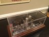
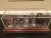
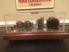
I even threw together an acrylic dust cover when not in operation. Feet are kinda dangerous still gotta file them a bit. But all in all, i like the way it came out cosmetically.


IMG_0922.JPG
 

Attachments

  • IMG_0921.jpg
    IMG_0921.jpg
    58.1 KB · Views: 24
  • IMG_0915.jpg
    IMG_0915.jpg
    66.3 KB · Views: 23
  • IMG_0923.jpg
    IMG_0923.jpg
    55.6 KB · Views: 25
  • IMG_0919.jpg
    IMG_0919.jpg
    57.1 KB · Views: 30
  • IMG_0920.jpg
    IMG_0920.jpg
    53.2 KB · Views: 31
I really appreciate all your advice guys. Yes, I'm new to the hobby, although I've been an audiophile for years and I'm actually IN radio.. My background is RF then moved on to Sat Radio where I've been now for 8 years..Which is funny, because I am just learning this stuff at 45 years old. And by the way... I'm hooked!! I have some good solid state stuff (Krell Showcase Amp and Pre, parasound 5 channel amp, with Yamaha A1000) but after hearing a good tube amp with a good turntable I was floored and now my man cave is filled with tube gear set up a small home lab and now waiting for me to learn more so I can work on it.
I've watched every youtube video of working safely (lol, don't wanna die).

Back to this fisher... Next up, I'm going to make sure all tubes are ok, and will post.

Thanks again!

-Tom
Tom,
It's great that you've discovered that "tube sound"!! I was a SS guy with my JVC receiver, CD player and cassette....then I got my first tube amp paired with a new TT with a MC cartridge...I was FLOORED!!! (just like you!!) LOL...Great, isn't it?? ALL the JVC junk is in the back closet now!! Gotta make room for The Fishers!
 
lovin it

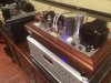
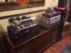
i got a chance this afternoon to push this amp a bit and run it through its paces.. overall, I'm very pleased with its sound, even with the old caps. I believe the coupling caps must have either been changed to ceramic discs at some point or the parts list is incorrect.. anyway, I'm still awaiting on the vitamin Qs.
I used it at first with just my iPhone and it really wasn't that bad, even my wife commented that it sounded pretty good. i hooked it up to my, what i thought, inefficient, Infinity Reference 2000.6 speakers and it kicked ass.
it really shined one i hooked it up to the Krell processor, and used the Ascend Sierra speakers. Very detailed, maybe a tiny bit on the bright side, just a tad. Not so much on the Infinity's.

Overture from The Who's Tommy on SACD sounded absolutely incredible!! You know it sounds good when you get goose bumps and chills up the back of your spine.
Just need to set up a phono preamp and hook up the table in the game room and i will check out vinyl on this amp, where i think it will shine even more.

I'm still using the Mullard $8 tubes in it. I may try the old Grommes 6BQ5s (not sure what make they really are). Next on my list is some 7189 Amperex tubes.

Thank you everyone who helped me with this project!

PS. The Valve book arrived from Amazon finally today Rich, got some reading to do.

-Tom
 

Attachments

  • IMG_0932.jpg
    IMG_0932.jpg
    71.1 KB · Views: 24
  • IMG_0933.jpg
    IMG_0933.jpg
    81 KB · Views: 22
  • IMG_0939.jpg
    IMG_0939.jpg
    71.7 KB · Views: 21
Back
Top Bottom