• The move to the new server is done. There are some software and database maintenance updates in process. This has us passing the hat around to help out. We appreciate any donations. Seriously, even a dollar helps. The payment page may be found here - https://www.audiokarma.org/support.html

Fisher 480a questions

Tom,
When you change the coupling caps you will really be surprised. As I've mentioned before, on that amp, it takes about 2 or 3 songs till the new PIO caps begin to bloom open. It's like a hash brownie kicking in (or so I've been told). And he tinny sound...that's those ceramics, I promise you. 7189 amperex will be hard to find and expensive. 6bq5/el84 amperex work fine in my amp. Best ones have the "D" getter (as compared to the "o" getter). Plenty of them out there labeled for "Hammond". Try and look at the codes for those made in Holland at the Herleen plant. A really clear sounding tube. If you're like me you'll like them so much that you'll pick up a spare quad. They blow away the newer tubes made in Russia.
Glad you're enjoying the amp!

Rich
 
Still loving this Amp

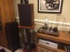
Loving this Fisher Amp. Been trying different vintage speakers with this amp and haven't found any it could not drive, and loud!
Favorites believe it or not are these beat up Dynaco A25s. I replaced the caps in them with some 5.1 uF Solens, and replaced the terminals, then new grill cloth (I know, not authentic, but it's what I had laying around) then finished off with some mahogany Howard's restor.

It doesn't sound half bad with the DCM Timeframes TF-1000 either, but I'm using them in the game room with the Harman Kardon HK250.

So far I've tried a few different caps in the amp. I ended up spending stoopid money on some Jensons as I couldn't find any .047 Vitamin Qs...(yet)

Tubes: so far I have tried the following:

Quad of Old RCAs (labeled Grommes) sounded the best
Quad of some odd Russian old stock 6P14P. Bought on auction for $2 each. Don't sound bad.
2 MiniWatt Philips mixed with 2 original Fishers- this combo runs a very close second to the RCAs.

Next on the list are some Amperex EL84s. Anyone know the best place to find any beside fleabay?

Thanks for listening, and thanks everyone that helped me with this Amp.

Tom

PS, Rich, I'm halfway through the book.. Went back and reread a few areas, but Imma learnin'
 

Attachments

  • image.jpg
    image.jpg
    70.5 KB · Views: 25
Which RCA outputs? I have a set that came from a Baldwin organ, smooth grey plates with a solid "pie plate" getter on the top that sound very nice. Just curious if yours happen to be the same.
 
Which RCA outputs? I have a set that came from a Baldwin organ, smooth grey plates with a solid "pie plate" getter on the top that sound very nice. Just curious if yours happen to be the same.

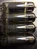
Here's a shot of them Gadge, they say "Made in the USA for Grommes by RCA"

They sound the best from what I have IMO. Very full sound.

-Tom
 

Attachments

  • image.jpg
    image.jpg
    74.5 KB · Views: 23
Tom,
When you change the coupling caps you will really be surprised. As I've mentioned before, on that amp, it takes about 2 or 3 songs till the new PIO caps begin to bloom open. It's like a hash brownie kicking in (or so I've been told). And he tinny sound...that's those ceramics, I promise you. 7189 amperex will be hard to find and expensive. 6bq5/el84 amperex work fine in my amp. Best ones have the "D" getter (as compared to the "o" getter). Plenty of them out there labeled for "Hammond". Try and look at the codes for those made in Holland at the Herleen plant. A really clear sounding tube. If you're like me you'll like them so much that you'll pick up a spare quad. They blow away the newer tubes made in Russia.
Glad you're enjoying the amp!

Rich

Hi Rich ---- I am also working on a Standalone Version of the Fisher 481A and have a few questions about what you did as shown in your 481A Pictures on Page 2 or 3 of this thread.

In your picture showing the Speaker Binding Posts and the "rewired 6-pin Molex" for the speakers:
a) How did you physically mount the Binding Posts on the top and bottom of the chassis? From the picture, it looks like you would have had to drill out four of the speaker strip screw holes in order to accommodate the thickness of the binding post and then on the bottom grind off what was left and in the way of the bottom plate of the binding post pair. Is this what you did, or something else?

b) From the picture, it looks like you removed the 6-pin Molex's Audio Signal Yellow and Orange Wires from the Tag Strip, then ran 2 new wires from where Y-O were on the strip back to the 2 Positive Binding Posts. Then what was originally connected to the Ground Positions of the speaker strips was left alone. There were 2 ceramic caps originally on the Tag Strip ..... did you remove them? I can't tell from the after picture??? Let me know!

c) From the picture it looks like you ran a wire from each EL84 pin #2 to a position of the 6-pin Molex so you could monitor each of their Bias Voltages. When I compared your Stock 481A Bottom Picture (with 250 Ohm 20W Resistor in the wrong place) with the After Speaker Terminal Mods it looked like the 4 resistors that were originally connected to Pin #2 changed. Did they? What value? Let me know.

In your picture of the area under the Power Transformer and the AC input Line After Modifications:
a) You cleaned out all but 2 pins of the 12-pin Molex (Ground and the Position with a Yellow wire). Was the Yellow wire and Ground wire left for monitoring and what is being monitored?????? Please let me know.

b) It looks like any component that connected to the missing positions of 12-pin Molex was not needed since the Tuner/Preamp/Phono are no longer present) and was surgically removed. Is this correct? Any other wiring changed or re-directions that I am missing? Please let me know.

c) You added a power switch in the circular hole that originally had wires for the Phono and Pilot Lite Wires and wired the switch back to the 2 AC input recepticals (J18 and J19 ...... I think????).

Please let me know if I am right or wrong..
Thanks Stew

 
Stew,
I don't have that amp anymore, but I'll try to remember what I did.
a) How did you physically mount the Binding Posts on the top and bottom of the chassis? From the picture, it looks like you would have had to drill out four of the speaker strip screw holes in order to accommodate the thickness of the binding post and then on the bottom grind off what was left and in the way of the bottom plate of the binding post pair. Is this what you did, or something else?
To remove the terminal strips, I used a dremel to cut the rivets and a nibbler to widen the opening to mount the binding posts.
b) From the picture, it looks like you removed the 6-pin Molex's Audio Signal Yellow and Orange Wires from the Tag Strip, then ran 2 new wires from where Y-O were on the strip back to the 2 Positive Binding Posts. Then what was originally connected to the Ground Positions of the speaker strips was left alone. There were 2 ceramic caps originally on the Tag Strip ..... did you remove them? I can't tell from the after picture??? Let me know!
I believe the molex connector closest to the speaker terminal strip was for the speaker selector. I ran the signal wires straight to the new binding posts. The molex connector was then re-purposed so I could measure the bias voltage (21v) from each EL84 pin 2 when adjusting the bias. That proved to be totally unnecessary as the voltage measured at pin 2 of each tube isn't as important as the voltage at the cathodes (pin 3) when setting the bias.
I wouldn't have removed or replaced the two 330pf ceramic caps. They may be difficult to see, but I'm sure they're there.
c) From the picture it looks like you ran a wire from each EL84 pin #2 to a position of the 6-pin Molex so you could monitor each of their Bias Voltages. When I compared your Stock 481A Bottom Picture (with 250 Ohm 20W Resistor in the wrong place) with the After Speaker Terminal Mods it looked like the 4 resistors that were originally connected to Pin #2 changed. Did they? What value? Let me know.
I think I replaced those resistors with something modern carbon film. Bringing a wire out from each pin 2 was just a "double check". The cathode voltage is more important in that amp.
I moved the 250 ohm resistor so it was under air vents and away from other components.
In your picture of the area under the Power Transformer and the AC input Line After Modifications:
a) You cleaned out all but 2 pins of the 12-pin Molex (Ground and the Position with a Yellow wire). Was the Yellow wire and Ground wire left for monitoring and what is being monitored?????? Please let me know.
The yellow wire should be monitoring the 33v cathode supply. That's the molex connector I used to measure and set the bias.
b) It looks like any component that connected to the missing positions of 12-pin Molex was not needed since the Tuner/Preamp/Phono are no longer present) and was surgically removed. Is this correct? Any other wiring changed or re-directions that I am missing? Please let me know.
Correct. I removed anything unnecessary.
c) You added a power switch in the circular hole that originally had wires for the Phono and Pilot Lite Wires and wired the switch back to the 2 AC input recepticals (J18 and J19 ...... I think????).
I'm not sure how I wired the SPST switch. I could have wired it to turn the amp off while leaving the AC outlets powered or (most likely) wired it to shut everything down.

Great sounding amp. The guy I sold it to loves it.
 
Oh my, this is one of the first threads I ever created, and first tube amps. I'm embarrassed to read through it..lol. Man, have I learned a lot from this place and people with the patience like Rich has.
I still have it, I use it everyday in my office at work. Still sounds awesome.
 
Back
Top Bottom