• The move to the new server is done. There are some software and database maintenance updates in process. This has us passing the hat around to help out. We appreciate any donations. Seriously, even a dollar helps. The payment page may be found here - https://www.audiokarma.org/support.html

Fisher 500C restoration and modification project

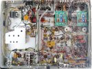
For a Fisher K-100 project (discussed briefly here) I built a a transistor buffered zener regulated power supply and an IBAM to control bias. Here I wanted to try Dave's EFB and IBBA swhich offers both balance and bias-level control. Wednesday’s report showing the underside with highlighted areas for the mods (post #71) couldn’t show the IBBA. It’s mounted on the top of the chassis in the area often used by others here.

Highlighted area B (post #71) showed where the cathode sense wires and the bias supply wires are bundled after leaving the output tube corral. They are combined with a ground lead (BLK) and the voltage lead (RED) from the EFB. That group is divided into two sets of 5 wires. As many have shown, the wires can come to the topside using holes around C92.

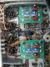
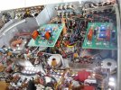
Here’s some photos of the IBBA make/install process.
lKuQ6X8.png

23agIIp.png

Today might see the start of work on the RIAA equalization circuit. -d
Did you make the IBBA pcb? Awesome looking work on the board!! I would love to source one from the talent pool…:)
 
Thanks so much for documenting everything! I am especially thankful for the detailed pictures and lay explanations. The tech talk on many of the mods was well beyond my grasp, so this info has been awesome. Thank you, OP!
 
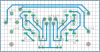
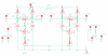
Bill - Sorry I am slow to reply. Work and family kept me away. Here’s the IBBA schematic and board layout drawings. 10 wires attach to the board. (1 GND, 1 BIAS V SOURCE, 4 WIRES FROM CATHODE RESISTORS, 4 WIRES TO GRIDS)..
IBBA Board.png
Ibba Schematic .png
I use Eagle PCB design software. The downloadable full feature demo comes with no charge but there is a size (4”x3”) and layer (2) limit after the demo period expires. I etch my own boards in this size/#ofcomponents range. I printed labels for the board on a transparency sheet. It’s held down by the components. I prefer this to decals for this type of board. If you use a PCB manufacturer (try JLCPCB - $20 for 5 copies of a board up to 4”x4”, delivered in 10 days!) you can have all labeling silk screened on board, no extra charge. -d
 
TAPE MON jacks to AUX input modification
I converted the TAPE MON jacks to use as an additional AUX input a couple of weeks ago after deciding I won’t need the tape monitor function in the future. Many here have done the same. Is it OK to alter Fisher’s ‘art’? For this unit my answer is already clear – like many of you I’ve gone far down the customization road. This project was never about restoring the 500C to be a museum-quality unaltered example of Fisher’s original product. This is more of a renovation than restoration. We want these beautiful receivers to be the best they can be and to have the functions needed for how we’ll use them.

This is a simple modification and the function created is very useful. With a flip of the switch the amp can alternate between a selected source and a second AUX source attached to the TAPE MON jacks.

pc4VDz8.png


STEP-BY-STEP (left channel)

Remove the 680K resistor (R52) that connects the left channel RECRDR OUT jack (J10) to GND. Remove the components R33 (330K) and C30 (120 pF) that are part of the original lead from the selector switch terminal 1F-8* to the TAPE MON jack (J9). Connect the TAPE MON jack directly and solely to the ‘ON’ side of the TAPE MONITOR switch. Disconnect selector switch terminal 1F-4 from the 470K/24pF component pair (R38/C31). Connect selector switch terminal 1F-4 to the ‘OFF’ side of the TAPE MONITOR switch. Connect the 470K/24pF pair (R38/C31) that is no longer connected to terminal 1F-4 to the center of the TAPE MONITOR switch. (The TAPE MON to AUX input conversion of the right channel follows the same process.) *See this post for an explanation of how selector switch terminals are named and located.

With these changes the TAPE MON jacks become an alternative AUX input that is active when the TAPE MONITOR switch is in the ‘ON’ position. Thanks to all who pioneered this mod and wrote about it here. -d

A bit late to this party, but my interpretation of this mod is to make the tape monitor (input) function like most pre-amps/receivers after about 1970 (probably earlier). Meaning that the Tape Mon input is the same as any other high level input, e.g. AUX. This will allow input from a "modern" tape machine. This would be useful not only as an additional AUX input, but if one wanted to connect the outputs of a tape deck to the Monitor In jacks, they can use the monitor function.

This seems like a much simpler mod than the TAPE HEAD to AUX mod, and yield similar functionality. Am I missing any "gotchas"?
 
Sabre. The Tape Monitor's are before the AUX and have a lower gain level by 1/2 stage. Moving it to the detailed area brings the gain up to the level of the AUX section so there isn't a difference in Sound level switching between the two. As built the 500c can handle a 3 head tape machine, just at a slightly lower volume than aux.
Larry
 
Go into the STICKIES at the top of the Forum. Click on "Technical Reference Threads" and you'll find a boatload of upgrades, updates, Mods, etc. Also check out the "800c Service Bulletin" link on the STICKIES FRONT PAGE.
 
Back
Top Bottom