daylite
Active Member
PCBs: IBBA......EFB......Buffer......Phase Inverter
TAPE MON to AUX input......Tone Control Bypass
TAPE HEAD input to AUX input
500C selector switch function animation
Loudness contour modeling and component selection
This project is close to an end. A signal strength meter problem came up but is now fixed.
Summary of Thread Contents
Introduction...................................................................................... Post #1
List of mods completed 8/29/2021 to 10/12/2021.............................Post #9
Dave Gillespie’s advice on normal signal meter levels.................... Post #12-#18
Troubleshooting and alignment advice from Dave........................... Post #23-#38
Advice on PCB clearances/update to mods completed................... Post #67
Schematic full map of this 500C project showing mods................... Post #69
Photos of 500C under chassis Before&After as of week 11............. Post #71
Parts purchased list for this 500C mod project as of week 11.......... Post #72
Images of make/install of IBBA printed circuit board......................... Post #73
Images of make/install of EFB printed circuit board.......................... Post #75
Images of make/install of Phase Inverter Circuit Mod PCB............... Post #76
Phase inverter adjustment using Wheatstone bridge........................ Post #77
Images of make/install of Preamp Buffer PCB.................................. Post #78
TAPE MON jacks to AUX input circuit mod....................................... Post #80
Tone Control Bypass modification..................................................... Post #81
TAPE HEAD input to AUX input conversion...................................... Post #87
'Final' schematic for this 500C project............................................. Post #97
Hi, all.
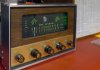
I have worked on only a few radios (RCA K130, Telefunken Rondo). Last year I received a Fisher K-100 chassis. I bought the K-100 chassis because of all I had learned here reading about Fisher products. Many of you will know the K-100 is very much like the Fisher 500 Mono. I recapped, modified the bias voltage supply, added a transistor buffered zener regulated individual bias control, added a tuning meter (the magic eye is faded), and built a front panel of wood and aluminum with backing plate for the knobs (the K-100 was used on consoles - I only had the chassis. Happily all brights and all knobs except one :-( were there.) Finished K-100 picture below. The sound was so great I dug out a turntable and speakers I bought in 1970 and I’m enjoying vinyl and great FM as I sit at the bench!
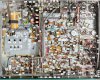
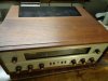
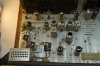
Last week USPS dropped off a Fisher 500C. It was great working on my first Fisher and I expect this will be a great adventure, too. I had a little panic when I opened the box and found one knob bright to be missing. Gave up looking through the packing, but the seller had shown a pic with all brights. Turned out it had gotten caught behind the dial glass and I heard it when I was moving the chassis up on end. Picture 2-4 below show some of the receiver. Picture 5 shows one of four PTs. Are these General Electric?
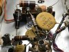
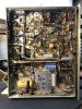
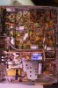
Seller said ‘all original’ but I doubt he took off the bottom panel. Picture 6 shows what I found. Someone had done a recap. (I guess it is all original, and then some.) First job for me is to reverse that. Picture 7 shows labels on the caps scattered around that replace C91 and C92. He/she kept C98. Looking at pic 6, does anyone recognize the replacement caps used? I’m just curious about how long ago the recap was done.
Other than the added caps a new R137 was added. It had to be way over on the right to bridge the recaps C91A/C91B. The original R137 is still under C91. More closeups are available if needed, but I want to wait until after removing the recaps before posting a quadrant photo series. There will be fewer pics per post in the future!
I’m not retired (just old) so progress may be mostly on weekends.
Thanks for reading. And thanks so much for all the knowledge shared and explanations found on this forum. I’ve read a lot of 500C relevant posts, but there's a lot more to see. I know I will need help with this project! I have a list of mods including 10R cathode resistors, 100 ohm screen stability resistors, IBAM, new output coupling caps, bypass resistor change (I read this may not be needed if IBAM is put in, but somewhere I think Dave said it could be ‘insurance’ ), RIAA upgrade, safety caps (C102,C103), CL-80, rectifier, upgrade R143, R139, R132, phase inverter (C69,C70), de-emphasis mod (R222, R223, R98), tuner (C85, C59, C61, C52-53, C57, C72), MPX (C210, C214, C221-222), phono preamp caps (C16, C17). The list for Mouser is about 45 line items!
Next post will be about reversing the recap (using Hayseed cans). After that the chassis will look better and I’ll be seeing what I expected to see when I took the bottom cover off.
(My apologies in advance for all the mistakes I will make or have already made!)
TAPE MON to AUX input......Tone Control Bypass
TAPE HEAD input to AUX input
500C selector switch function animation
Loudness contour modeling and component selection
This project is close to an end. A signal strength meter problem came up but is now fixed.
Summary of Thread Contents
Introduction...................................................................................... Post #1
List of mods completed 8/29/2021 to 10/12/2021.............................Post #9
Dave Gillespie’s advice on normal signal meter levels.................... Post #12-#18
Troubleshooting and alignment advice from Dave........................... Post #23-#38
Advice on PCB clearances/update to mods completed................... Post #67
Schematic full map of this 500C project showing mods................... Post #69
Photos of 500C under chassis Before&After as of week 11............. Post #71
Parts purchased list for this 500C mod project as of week 11.......... Post #72
Images of make/install of IBBA printed circuit board......................... Post #73
Images of make/install of EFB printed circuit board.......................... Post #75
Images of make/install of Phase Inverter Circuit Mod PCB............... Post #76
Phase inverter adjustment using Wheatstone bridge........................ Post #77
Images of make/install of Preamp Buffer PCB.................................. Post #78
TAPE MON jacks to AUX input circuit mod....................................... Post #80
Tone Control Bypass modification..................................................... Post #81
TAPE HEAD input to AUX input conversion...................................... Post #87
'Final' schematic for this 500C project............................................. Post #97
Hi, all.
I have worked on only a few radios (RCA K130, Telefunken Rondo). Last year I received a Fisher K-100 chassis. I bought the K-100 chassis because of all I had learned here reading about Fisher products. Many of you will know the K-100 is very much like the Fisher 500 Mono. I recapped, modified the bias voltage supply, added a transistor buffered zener regulated individual bias control, added a tuning meter (the magic eye is faded), and built a front panel of wood and aluminum with backing plate for the knobs (the K-100 was used on consoles - I only had the chassis. Happily all brights and all knobs except one :-( were there.) Finished K-100 picture below. The sound was so great I dug out a turntable and speakers I bought in 1970 and I’m enjoying vinyl and great FM as I sit at the bench!
Last week USPS dropped off a Fisher 500C. It was great working on my first Fisher and I expect this will be a great adventure, too. I had a little panic when I opened the box and found one knob bright to be missing. Gave up looking through the packing, but the seller had shown a pic with all brights. Turned out it had gotten caught behind the dial glass and I heard it when I was moving the chassis up on end. Picture 2-4 below show some of the receiver. Picture 5 shows one of four PTs. Are these General Electric?
Seller said ‘all original’ but I doubt he took off the bottom panel. Picture 6 shows what I found. Someone had done a recap. (I guess it is all original, and then some.) First job for me is to reverse that. Picture 7 shows labels on the caps scattered around that replace C91 and C92. He/she kept C98. Looking at pic 6, does anyone recognize the replacement caps used? I’m just curious about how long ago the recap was done.
Other than the added caps a new R137 was added. It had to be way over on the right to bridge the recaps C91A/C91B. The original R137 is still under C91. More closeups are available if needed, but I want to wait until after removing the recaps before posting a quadrant photo series. There will be fewer pics per post in the future!
I’m not retired (just old) so progress may be mostly on weekends.
Thanks for reading. And thanks so much for all the knowledge shared and explanations found on this forum. I’ve read a lot of 500C relevant posts, but there's a lot more to see. I know I will need help with this project! I have a list of mods including 10R cathode resistors, 100 ohm screen stability resistors, IBAM, new output coupling caps, bypass resistor change (I read this may not be needed if IBAM is put in, but somewhere I think Dave said it could be ‘insurance’ ), RIAA upgrade, safety caps (C102,C103), CL-80, rectifier, upgrade R143, R139, R132, phase inverter (C69,C70), de-emphasis mod (R222, R223, R98), tuner (C85, C59, C61, C52-53, C57, C72), MPX (C210, C214, C221-222), phono preamp caps (C16, C17). The list for Mouser is about 45 line items!
Next post will be about reversing the recap (using Hayseed cans). After that the chassis will look better and I’ll be seeing what I expected to see when I took the bottom cover off.
(My apologies in advance for all the mistakes I will make or have already made!)
Attachments


Last edited: