

You are using an out of date browser. It may not display this or other websites correctly.
You should upgrade or use an alternative browser.
You should upgrade or use an alternative browser.
Fisher 500C restoration and modification project
- Thread starter daylite
- Start date


I stand corrected then -- the current abbreviation then would be MHz -- that's a new one on me. Thanks Fred.
Dave
Dave

daylite
Active Member
Dave – I’m glad and thankful to be able to report the alignment is done and the tuning/sensitivity/fidelity are better than ever. Your instructions were essential! From what I learned I think most of the misadjustment was with the oscillator, but some of the IF filters were out of alignment, too. The problem with the sudden silence when dialing up the scale was front end related. I discovered I could move the point where reception stopped by front end adjustments. I was worried about the 6HR6 tube thinking it might have been the cause of the burned resistor R51, but wanted to try it again, so I attached a thermocouple to the new R51 and brought things up with a Variac while monitoring temperature. No problem, no heat. I’m using the 6HR6 now.
Tracking is good across the dial. On stations the meter is often at 3.9 and it drops to the bottom below stations. Only seen it above 4 a few times. Maybe conditions have not been good (it’s been rainy). After working on mods for a while I may return to this and try to get the signal/voltage even higher. But since it never exceeded 1.1-1.2 in the past this is a great outcome.
Thanks again – now on to the EFB! -d
BTW I made things easier on myself by building a turntable for the bench to hold the chassis. Much easier to work with! Thanks to Larry for describing that. Oh – and I did try a sweep and scope to look at each IF stage (just looking, not tweaking). You’re right – those transformers are excellent, nice bandpass. Way better than what I was used to seeing on the older mono receivers.
Tracking is good across the dial. On stations the meter is often at 3.9 and it drops to the bottom below stations. Only seen it above 4 a few times. Maybe conditions have not been good (it’s been rainy). After working on mods for a while I may return to this and try to get the signal/voltage even higher. But since it never exceeded 1.1-1.2 in the past this is a great outcome.
Thanks again – now on to the EFB! -d
BTW I made things easier on myself by building a turntable for the bench to hold the chassis. Much easier to work with! Thanks to Larry for describing that. Oh – and I did try a sweep and scope to look at each IF stage (just looking, not tweaking). You’re right – those transformers are excellent, nice bandpass. Way better than what I was used to seeing on the older mono receivers.
Glad you got it straightened out! It sounds like your unit was one that someone "fiddled with" to try and fix an issue. Invariably, that always leaves the unit in worse shape than where it started from.
Congrats on getting it going!
Dave
Congrats on getting it going!
Dave

fred soop
Super Member
Here is the link to the metric prefixes:
https://www.nist.gov/pml/weights-and-measures/metric-si-prefixes
Anything greater than unity is upper case except kilo (10^3), hecto (10^2), and deka (10^1). All that are less than unity are lower case. Some of these were added or clarified as late as 1960 and would probably have taken a while to propagate through industry. Fisher and others did use lower case "m" for mega, probably until Hz came into use.
https://www.nist.gov/pml/weights-and-measures/metric-si-prefixes
Anything greater than unity is upper case except kilo (10^3), hecto (10^2), and deka (10^1). All that are less than unity are lower case. Some of these were added or clarified as late as 1960 and would probably have taken a while to propagate through industry. Fisher and others did use lower case "m" for mega, probably until Hz came into use.

Eric&O
New Member
Hi, all.
This is my first post here. I have worked on a few radios (RCA K130, Telefunken Rondo). Last year I received a Fisher K-100 chassis. I bought the K-100 chassis because of all I had learned here reading about Fisher products. Many of you will know the K-100 is very much like the Fisher 500 Mono. I recapped, modified the bias voltage supply, added individual bias control, added a tuning meter (the magic eye is faded), and built a front end panel (only had the chassis though all brights and all knobs (except one) were there). Picture 1 below. The sound was so great I dug out a turntable and speakers I bought in 1970 and I’m enjoying vinyl and great FM as I sit at the bench!
Last week USPS dropped off a Fisher 500C. It was so great working on my first Fisher. I expect this will be a great adventure, too. I had a little panic when I opened the box and could not find one knob bright. Gave up looking through the packing, but the seller had shown a pic with all brights. Turned out it had gotten caught behind the dial glass and I heard it when I was moving the chassis up on end. Picture 2-4 below show something of it. Picture 5 shows the PTs. Are these General Electric?
Seller said ‘all original’ but I doubt he took off the bottom panel. Picture 6 shows what I found. Someone had done a recap. (I guess it is all original, and then some.) First job for me is to reverse that. Picture 7 shows labels on the caps scattered around that replace C91 and C92. He/she kept C98. Looking at pic 6, does anyone recognize the replacement caps used? I’m just curious about how long ago the recap was done.
Other than the added caps a new R137 was added. It had to be way over on the right to bridge the recaps C91A/C91B. The original R137 is still under C91. More closeups are available if needed, but I want to wait until after removing the recaps before posting a quadrant photo series. There will be fewer pics per post in the future!
I’m old but not retired, so progress may be mostly on weekends.
Thanks for reading. And thanks so much for all the knowledge shared and explanations found on this forum. I think I’ve read 90% of 500C relevant posts. I know I will need help with this project! I have a list of mods including 10R cathode resistors, 100 ohm screen stability resistors, IBAM, new output coupling caps, bypass resistor change (I read this may not be needed if IBAM is put in, but somewhere I think Dave said it could be ‘insurance’ ), RIAA upgrade, safety caps (C102,C103), CL-80, rectifier, upgrade R143, R139, R132, phase inverter (C69,C70), de-emphasis mod (R222, R223, R98), tuner (C85, C59, C61, C52-53, C57, C72), MPX (C210, C214, C221-222), phono preamp caps (C16, C17). The list for Mouser is about 45 line items!
Next post will be about reversing the recap (using Hayseed cans). After that the chassis will look better and I’ll be seeing what I expected to see when I took the bottom cover off.
(My apologies in advance for all the mistakes I will make or have already made!)
Eric&O
New Member
Wow, this is a great thread, a great list of components and interesting discussion for the 500C! I am a bit of a newbie in all this, could someone please tell how important safety caps are for C102 and C103? Are the original components safety caps? What are you protecting using safety capacitors? Mine were big black ones with yellow writing. I replaced them with standard film capacitors. Was that OK to do? Thanks!

thornev
Super Member
C103 is known as the Death Capacitor. "To be safe from ground shocks, the so-called "death cap" should connect to the neutral wire of the power cord, not the hot. But, back in the day, there was no way to tell which wire was which."
"There were many radio chassis back in the day that had the ground side of the AC lead connected directly to the chassis. When those were plugged in backwards the chassis was seeing 100% AC. The user was protected by not having access to the chassis. Knobs were plastic as was the front of the casing."
It is critical to replace it. I replaced mine with a KEMET 300 vac 0.01uF 10%. Note it is an AC voltage cap, not DC. Here's some education:
What was the purpose of the so-called "death cap"? | Audiokarma Home Audio Stereo Discussion Forums
What is the "death cap" on vintage amps? | The Gear Page
"There were many radio chassis back in the day that had the ground side of the AC lead connected directly to the chassis. When those were plugged in backwards the chassis was seeing 100% AC. The user was protected by not having access to the chassis. Knobs were plastic as was the front of the casing."
It is critical to replace it. I replaced mine with a KEMET 300 vac 0.01uF 10%. Note it is an AC voltage cap, not DC. Here's some education:
What was the purpose of the so-called "death cap"? | Audiokarma Home Audio Stereo Discussion Forums
What is the "death cap" on vintage amps? | The Gear Page
Last edited:

Daylite: Turntable? Got a link? I'm having a senior moment here.
Eric&O
New Member
Hi Thorne, thanks so much for the direction on this and a lot of excellent reading. I especially like the “ABCs of Safety Capacitors” on justradios.com. Very helpful to the layperson, which I am. Also, I’d like to tell you how much we have used your PHOTOFACT sheet! I printed a 18” x 18” copy of it and it resides on the workbench, used it to help us install several capacitors in our 500c. Thank you, EricC103 is known as the Death Capacitor. "To be safe from ground shocks, the so-called "death cap" should connect to the neutral wire of the power cord, not the hot. But, back in the day, there was no way to tell which wire was which."
"There were many radio chassis back in the day that had the ground side of the AC lead connected directly to the chassis. When those were plugged in backwards the chassis was seeing 100% AC. The user was protected by not having access to the chassis. Knobs were plastic as was the front of the casing."
It is critical to replace it. I replaced mine with a KEMET 300 vac 0.01uF 10%. Note it is an AC voltage cap, not DC. Here's some education:
What was the purpose of the so-called "death cap"? | Audiokarma Home Audio Stereo Discussion Forums
What is the "death cap" on vintage amps? | The Gear Page
thornev
Super Member
Eric - Glad to hear you're making progress. The people on this forum are some of the most amazing with knowledge, skills and most importantly, a willingness to help others. And hardly a negative emotion is displayed which shows how much integrity there exists around these parts. AK Fisher forum is a gold mine for Fisher enthusiasts, from novice to expert. And FUN too !
Eric&O
New Member
Hi Thorne, when I look up “KEMET 300 vac 0.01uF 10%” on Mouser, it only shows a capacitor with short leads indicating it’s for a printed circuit board. Did you use a version with longer leads on it? My solder skills might struggle attaching extension leads to something like that. Thank youEric - Glad to hear you're making progress. The people on this forum are some of the most amazing with knowledge, skills and most importantly, a willingness to help others. And hardly a negative emotion is displayed which shows how much integrity there exists around these parts. AK Fisher forum is a gold mine for Fisher enthusiasts, from novice to expert. And FUN too !
thornev
Super Member
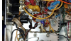
Eric - I looked for my notes on it and I believe what I did was to extend each of the short leads to make it easier to position inside the chassis. Or if extending was not needed then I soldered it as is. I don't really remember. I think I've circled mine in the attached image, but I'm unsure. It's been a long time.
Attachments
Eric&O
New Member
OK good enough thanks for all your help. They look like they are about 67 cents each so I’ll get a few to in case I mess up extending those leads.Eric - I looked for my notes on it and I believe what I did was to extend each of the short leads to make it easier to position inside the chassis. Or if extending was not needed then I soldered it as is. I don't really remember. I think I've circled mine in the attached image, but I'm unsure. It's been a long time.
fred soop
Super Member
To extend leads, bend the component lead into a "J". Do the same with the extension wire. Hook the "J"s together and crimp until tight. Then solder the connection. Done that many times, especially in the early days when many of our resistors and small capacitors were clipped from scrapped TV chassis.
Eric&O
New Member
Great Tip, Thanks Fred!To extend leads, bend the component lead into a "J". Do the same with the extension wire. Hook the "J"s together and crimp until tight. Then solder the connection. Done that many times, especially in the early days when many of our resistors and small capacitors were clipped from scrapped TV chassis.
daylite
Active Member
Eric - Here's the Mouser URL for the safety caps I used. They came with pretty long leads. Maybe 1.5 inches. (Sorry I have been away.)
Safety capacitors, 0.01 uF C102, C103
2 C102 C103
HTTPS://WWW.MOUSER.COM/PRODUCTDETAIL/VISHAY-DRALORIC/WYO103MCMCF0KR?QS=SGAEPIMZZMU3DWSQD4TL0KILG1SXUDO4FBMPL%252BKOKSK%3D
Safety capacitors, 0.01 uF C102, C103
2 C102 C103
HTTPS://WWW.MOUSER.COM/PRODUCTDETAIL/VISHAY-DRALORIC/WYO103MCMCF0KR?QS=SGAEPIMZZMU3DWSQD4TL0KILG1SXUDO4FBMPL%252BKOKSK%3D
daylite
Active Member
Daylite: Turntable? Got a link? I'm having a senior moment here.
Larry - found it! Wasn't easy (just try searching for 'turntable' on this site)! Lucky it's also known as a lazy susan.
https://audiokarma.org/forums/index...d-fm-dial-pointer.920611/page-3#post-13940904
Last edited:
Eric&O
New Member
Very nice. Thank you Daylite…I noticed the Kemet capacitor has 10% tolerance and the Vishay capacitor has a 20% tolerance. Does anyone know if a difference in safety capacitor tolerance of 10% vs 20% matters in the 500C C102 / C103 application?Eric - Here's the Mouser URL for the safety caps I used. They came with pretty long leads. Maybe 1.5 inches. (Sorry I have been away.)
Safety capacitors, 0.01 uF C102, C103
2 C102 C103
HTTPS://WWW.MOUSER.COM/PRODUCTDETAIL/VISHAY-DRALORIC/WYO103MCMCF0KR?QS=SGAEPIMZZMU3DWSQD4TL0KILG1SXUDO4FBMPL%252BKOKSK%3D