daylite
Active Member
Tone Control Bypass Modification
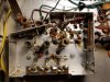
The bypass removes the Baxandall BASS and TREBLE tone controls from both left and right signal paths. These notes and part numbers are for the Fisher 500C LEFT channel. The RIGHT channel will involve the same changes.

STEP-BY-STEP (left channel)
1. The LOW FILTER (LF) switch components are disconnected and then reconnected ‘off-switch’ with C39 (20 nF) wired parallel to C38 (2200 pF). This renders the LF function permanently ‘OFF’. The LF switch is left empty.
2. One side of the LF switch is bridged end-to-end with an 8pF cap and a 1.2M resistor, in parallel. The black wire that connected to the center terminal of the LF switch (and to C38/C39) is moved to an end position on the LF switch and the lead from PC3 Pin 7 is moved from the center of the TAPE MONITOR switch to that same end of the LF switch. The other end of the LF switch is connected to the ON end of the HIGH FILTER (HF) switch. [The LF switch still moves but now has no function. Its terminals are being used only as mounting posts.] The lead running from PC3 Pin 4 to R72/C47 (220K/100pF) is disconnected. PC3 Pin 4 is then connected to the ‘OFF’ side of the HF switch and the lead from R72/C47 is connected to the center of the HF switch.
This is another very desirable circuit modification. It allows the user to immediately hear output with and then without the Baxandall tone control circuits in play. Many thanks and all respect to Dave Gillespie and those who have written here about their experience with this mod. -d
The bypass removes the Baxandall BASS and TREBLE tone controls from both left and right signal paths. These notes and part numbers are for the Fisher 500C LEFT channel. The RIGHT channel will involve the same changes.
STEP-BY-STEP (left channel)
1. The LOW FILTER (LF) switch components are disconnected and then reconnected ‘off-switch’ with C39 (20 nF) wired parallel to C38 (2200 pF). This renders the LF function permanently ‘OFF’. The LF switch is left empty.
2. One side of the LF switch is bridged end-to-end with an 8pF cap and a 1.2M resistor, in parallel. The black wire that connected to the center terminal of the LF switch (and to C38/C39) is moved to an end position on the LF switch and the lead from PC3 Pin 7 is moved from the center of the TAPE MONITOR switch to that same end of the LF switch. The other end of the LF switch is connected to the ON end of the HIGH FILTER (HF) switch. [The LF switch still moves but now has no function. Its terminals are being used only as mounting posts.] The lead running from PC3 Pin 4 to R72/C47 (220K/100pF) is disconnected. PC3 Pin 4 is then connected to the ‘OFF’ side of the HF switch and the lead from R72/C47 is connected to the center of the HF switch.
This is another very desirable circuit modification. It allows the user to immediately hear output with and then without the Baxandall tone control circuits in play. Many thanks and all respect to Dave Gillespie and those who have written here about their experience with this mod. -d
Last edited:


 thanks, Larry!